
During the month of July, I dedicated myself to the remodeling project, with the objective of finishing the retaining wall back yard so I could start preparing for the final push to get the brick patio done. I was all in. I took a “sabbatical” from my church choir, stopped cooking on the weekends, and worked on the project on weekdays when I got home. I got pretty close. Because this was my second shot at a retaining wall, I learned some more streamlined and efficient methods, plus I used my laser level system that I got for Father’s Day. The results were really good, as you can see in the following video.
One of the major design objectives of my home remodeling project was to build a water-friendly landscape. This resulted the inclusion of a lot of hardscape, surrounded by planters that would be planted with drought-tolerant plants and watered using a drip irrigation system. However, I had a bit of a conundrum with my existing fruit trees. Fruit trees, especially citrus, would need a lot of drippers running almost constantly to get the desired amount of water in the hot months. While a drip system would be much better than the sprinkler system that I was tearing out, the amount of water was still pretty horrendous — especially when compared to the new drought friendly plants I was planning on. Fortunately, while I was doing my research on irrigation design, I ran across the concept of using the greywater from my home. I stumbled across the “San Francisco Greywater Design Guide” that was pretty comprehensive, and as I continued down this line of thinking, I found out that my own city (Chula Vista, CA) had greywater design guides and permitting rules as well. Best of all, if you just keep the system simple and use only your laundry greywater, you don’t need a permit and the project becomes something well within the realm of a DIY’er. I wrote about this system in a previous blog entry (Irrigation and How A Project Expands) which goes into more detail about why this is a good idea.
The design of a laundry greywater system is fairly straightforward. The most complex part of the whole deal is getting a 3-way ball valve, also known as a diverter valve, and installing it such that the effluent of your washing machine can be “diverted” to either your landscape, or to your sewer system, where it normally goes. More on that later. Once diverted from sewer, the greywater needs to get outside the house and out to wherever you plan on irrigating with greywater. This is where things get problematic for existing homes that want to retrofit the system. If you’re having to burrow under driveways, sidewalks, or through slabs, then the cost quickly outweighs the benefit. There are probably some imaginative ways to get the water from here to there, but in reality, unless you plan on this during the construction phase of your home, or during a major remodel, then this part will likely be a deal-breaker. Fortunately, because this was a major remodel, I had things outside torn up sufficiently such that burying some extra piping for this greywater system was no big deal. Hey, this is a big modernization project and so, why not do my best to get up to contemporary standards? Here are some pictures of the installation of the piping from the house to the back.
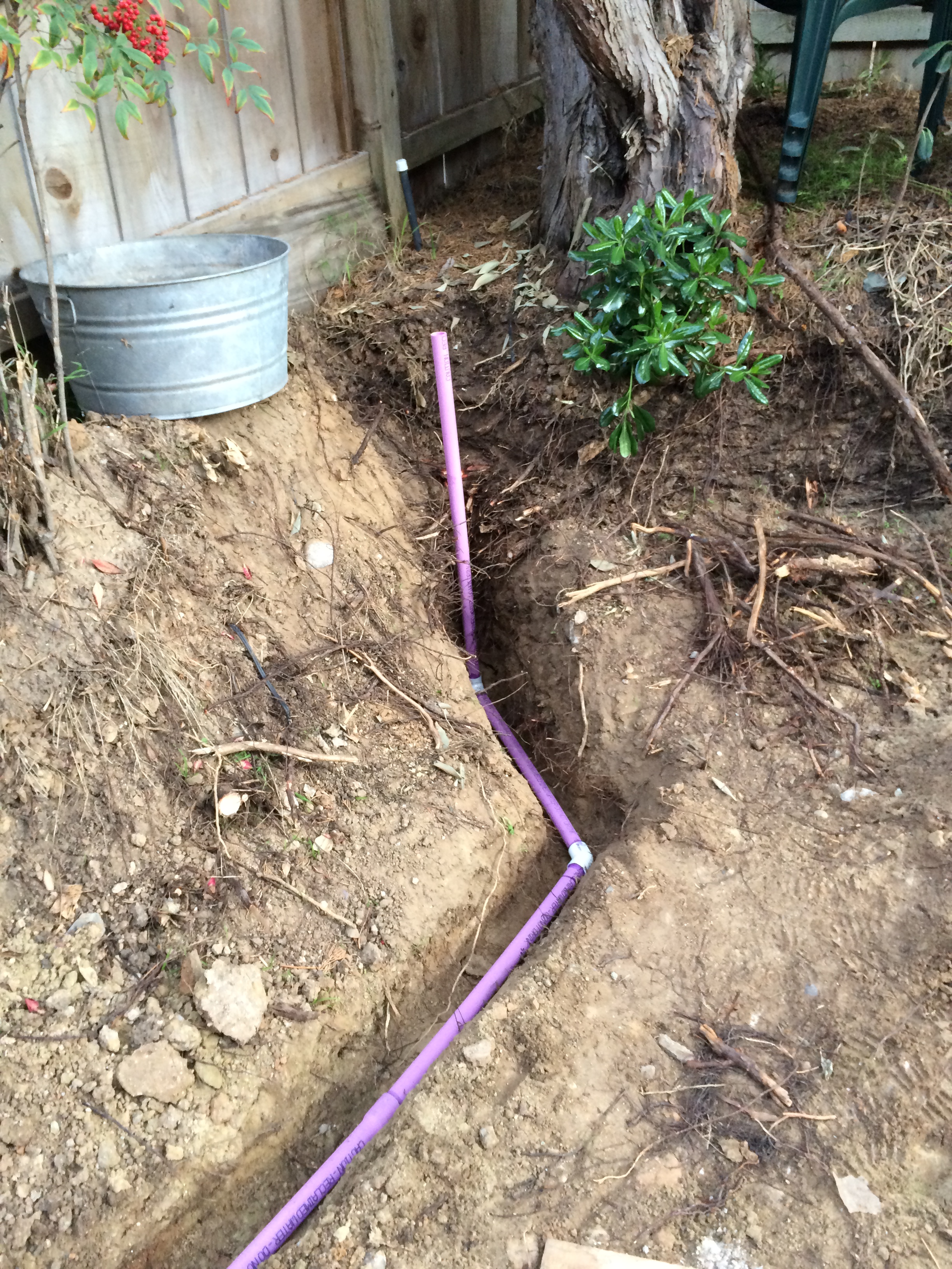
This is the supply line coming up into the back. It is routed under where the retaining wall will be.

The greywater supply line showing where the line will exit the house and routed to the back yard. I took advantage of the fact that I already had the ditch dug for the site drainage system.
Next is the water distribution system. Most of the literature I found on the subject showed a bunch of upside-down plastic flower pots that were repurposed to cover a greywater outlet and then had these troughs filled with bark mulch surrounding each tree that, in theory, would provide an even distribution of water around each tree. I did not like the bark mulch idea because it decomposes over a relatively short period of time, so every 3-4 years or so, you’d have to go in and basically re-do that part of your water distribution system. However, I remember one of the first “projects” my dad doing when I was little was the installation of a drywell for laundry effluent. We had just moved to a place in the “country”, which is now considered part of the ex-urb of Detroit, and our laundry basically discharged out to the grass in back. To get this working properly, he re-did the drainage piping and then dug a big hole and filled it with gravel. The laundry effluent would go into the gravel bed and have time to disperse into the ground. Not really necessary for irrigation because we were in southeast lower Michigan, but the principle would still apply in my situation. The more I thought about it, the more I liked the idea. A gravel bed has an advantage over bark mulch in that it doesn’t decompose. However, I didn’t want to fill my backyard with gravel, so I came up with the idea of a series of “mini” dry wells that would be arrayed around my trees as best as I could manage. This, fortunately, turned out to be a straight line, as shown in the following picture.
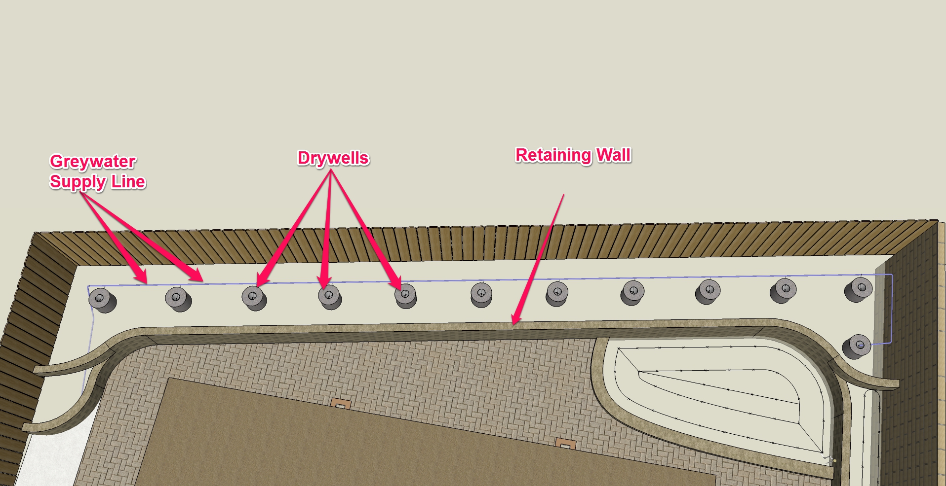
Drywell Layout. I had a long, narrow area to irrigate, so this seemed to be an optimum design.

Here is a picture of the final installation. Note that I had to switch the side where the supply pipe came in. Sometimes you deviate from the plans, especially when it makes sense.
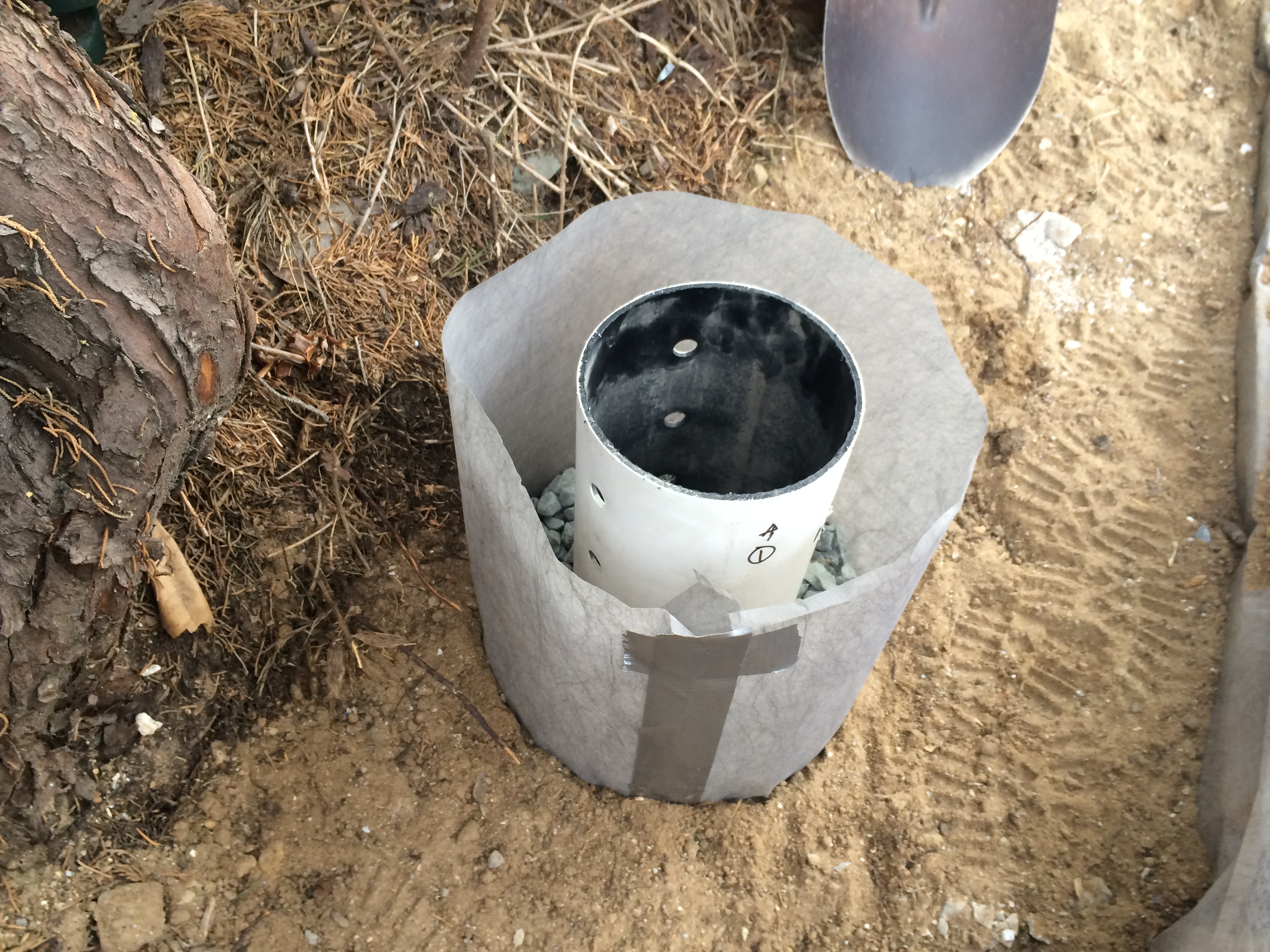
One of the things that a greywater distribution system needs is a manner of controlling the flow to each discharge point. This is because, due to the nature of fluid flow, if you just hook pipes together, the distribution will be uneven as the outlets closest to the source will discharge a disproportionately larger amount of water due to the higher pressure of the water as it is closer to the source. So, the basic drywell concept had to be modified to allow access to a valve to regulate the flow. I came up with an idea of a perforated drain pipe that would house the valve, with an annulus of gravel around it. The water would enter the standpipe, and the holes would direct the water into the surrounding gravel, which would then be absorbed by the surrounding soil. I also didn’t want any of the roots to infiltrate the gravel bed, so I decided to surround the entire assembly with landscape fabric. A circular concrete paver on top would provide a decorative finish, as well as access for future adjustments and maintenance. Here is a schematic of the basic “mini” drywell design.

Anatomy of a laundry water mini-drywell. I know what you’re saying — why do I use a cardboard concrete form? Well, read on. It’s really a great idea.
So, now, with the design all set, all I had to do was build it.
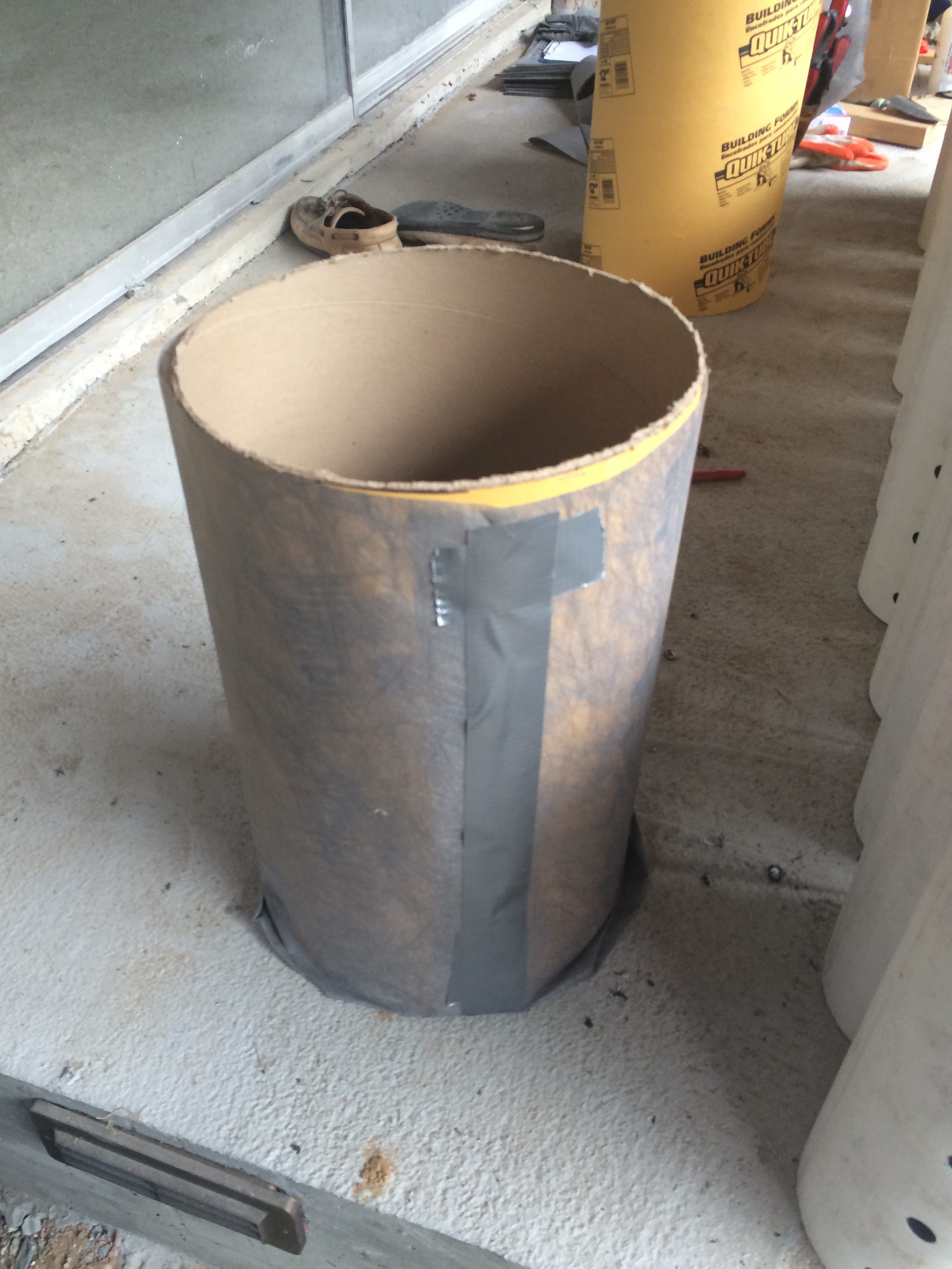
Whenever installing something that is connected together, be it pipes, electrical wires, data lines, whatever — always start with the placement of the endpoints of the connections first. I know this seems obvious, but focusing on this aspect of the installation helps me figure out the right sequence. In this case, I had to dig holes, and then somehow fill them with gravel and stick a standpipe in. I also had to fuss with that landscape fabric. But, I didn’t want to do the backfill, and then have to dig it up once again to make these holes. So, I came upon the idea of making a self-contained form that I could set in the ground, do the backfill around it, pour in a couple of inches of gravel, set the standpipe in, and then fill around the standpipe and withdraw form. This had the advantage of making it easy to wrap landscape fabric around the form so that all I had to do was pull out the form, and I’d have a perfectly centered standpipe, surrounded by an annulus of gravel and close fitting landscape fabric. Here is how I prepared the forms:

Step #1: Cut the landscape fabric to 3.5x the diameter of the form in length and the height of the form plus one diameter in width.

Step #2: Align one edge of the landscape fabric with the top edge of the form and roll it up into a neat cylinder. Secure the edges with wide tape. I used duct tape, but probably any tape could be used. This only temporary as the backfill will hold everything in place once installation is complete. DO NOT TAPE TO THE FORM! You will never get the form out later and you will be very sad.

Step #3: Fold one end of the landscape fabric in like you’re wrapping a birthday present. Fold the opposite end toward you. You will have two fabric “ears”.

Step #4: Tape each “ear” to the side of the form. You will have a neatly made bottom of landscape fabric when you’re done.

Step #5: Tack the loose edges of the landscape fabric to the bottom with a couple of pieces of tape.
Here is the form, all finished. I made two of these and then sequentially installed them into the landscape.
The next thing to do was to prepare the standpipes. I had a total of 12 wells, so I needed 12 standpipes. The dimensions of my wells were 18″ tall by 12″ in diameter, but since I wanted 2″ of gravel underlayment, my standpipes were only 16″. These standpipes are actually repurposed 6″ perforated hard PVC drain pipe. This means that (a) it is made of sturdy PVC and (b) it has two lines of holes oriented at 90° to each other. This gives the water some direction because, well, there are 360° in a circle, and this only covers ¼ of that, so by sheer mathematical principle, the flow will be directional. Except that the gravel will disperse the flow, so the effect is not that great. I digress. Bottom line is that you have a pipe with pre-drilled holes, so that saves you labor. To a point. There still must be a way for the water to enter the standpipe, and that will be via a branch from the supply line. SO… you have to drill a hole to allow the supply line to penetrate, preferably opposite the two rows of holes so you can pretend that you’re directing the water in the direction that you wish. No problem, you say. But, there is one more consideration, and that is elevation. Ideally, you do not want to have to force your water uphill. That will create unnecessary stress on your washing machine pump, and if your situation is such that the closest land is on the “downhill” side, then you need to put a solid pipe to the highest point in your system, and distribute downhill from there. If you don’t understand what I’m talking about, then please just trust me. The net effect (for me) was to locate the holes for the individual supply lines at an ever decreasing level so I could have a natural slope. I took the distance between the first and last drywell, and then multiplied it by the % slope that I wanted (anything between 1% and 2% is good). For ease of measurement, I came up with a slope of 10″ over 50′ which turns out to be 1.7%. It’s all good! I then put a flag marker in each place where I wanted to put a drywell and measured the distance between each one. Multiplying the distance (in inches) by 1.7% (or 0.017 — easy to do on a calculator), gave me the difference in height. Here is a picture of the finished standpipes with the holes drilled at the correct heights.

This shows the relative height of the holes for branch lines, which gives a slope for the water to drain once the washing machine pump turns off. Best to number them as well so you can keep track when you do the installation. See the purple pipe? This is the correct color and has the correct labeling for a greywater irrigation system. I had to go to a specialty irrigation supplier to get this stuff. But, it’s required by code!
Now, it’s time to do the actual installation, I begin with digging a relatively shallow hole in the vicinity where I marked the drywell to go. I then insert the fabric wrapped form into the hole and check the level. I want the top of the drywell to be the same height as the finished retaining wall. Since I am putting 2″ caps on the retaining wall, and putting 2″ concrete stepping-stones over the drywells, the net effect is to see a series of stepping-stones among a bed of bark mulch, with everything level. Once the form is in place and leveled, I add 2″ of gravel to the bottom. This serves not only to stabilize the form, but also to provide a way for the water to disperse downward. I then center the standpipe and pour enough gravel around the standpipe to reach the bottom of the hole I drilled for the branch pipe. After all, I don’t want to be have to rout through the gravel to install the branch pipe and valve. I then backfill and pull the form off. And then on to the next one. Here are some pictures.

Step #1: Insert the form and set the level. The level of the retaining wall is two courses lower (8″) than the finished height, so I use an 8″ block on the existing course to get the level right. Making up 4″ and 8″ blocks of wood is another way that helped streamline my building process because these are considerably lighter than the actual bricks themselves. (Think 0.25 lb versus 26 lb.)
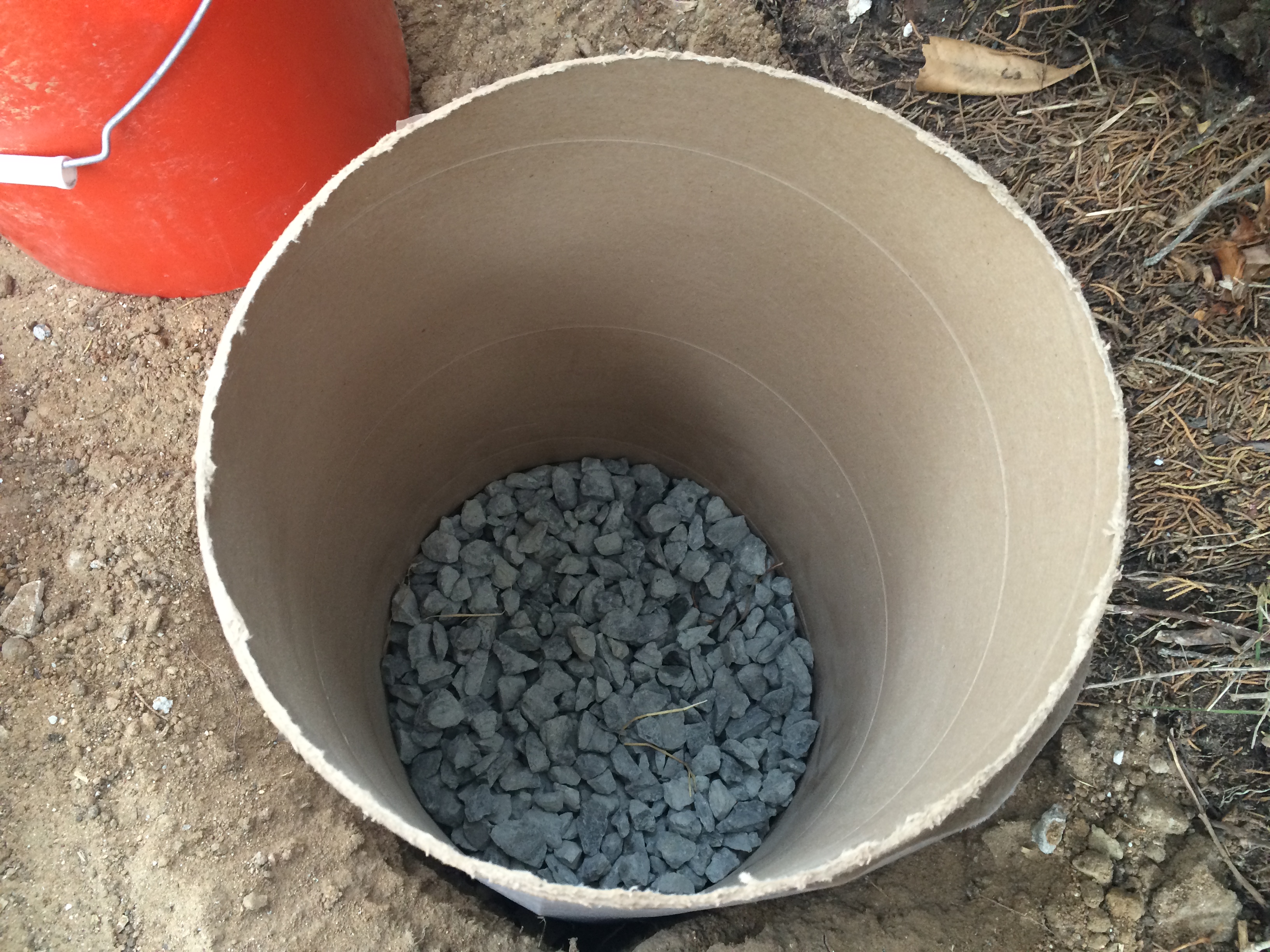
Step #2: Pour a 2″ gravel base. It helps if you mark a line 2″ from the bottom of the form with a sharpie. Just make sure you put the fabric on the right way!

Step #3: Insert and center the standpipe. Make sure the hole you drilled for the branch supply line is oriented perpendicular (facing) to where you intend the line to run. It helps to wiggle it around a bit to embed it in the gravel base so that it will withstand the pouring of the gravel around it.

Step #4: Pour gravel around the outside of the standpipe up to the hole you drilled for the branch line. Then backfill up to that level, ensuring that you tamp the backfill down well to minimize the inevitable shifting that occurs as things settle out.
Step[ #5: Remove the form by pulling upwards. This can be tricky because you need to grip the form without gripping the landscape fabric. Wiggle it around a bit, and it should slide right out.
The next step is to install the pipes. Basically, this design is a series of 1″ PVC pipes that have 1″ to 1/2″ PVC tees at each drywell. The 1/2″ pipe terminates with a 1/2″ ball valve in each drywell, which is used to balance the flow. Here is a picture:
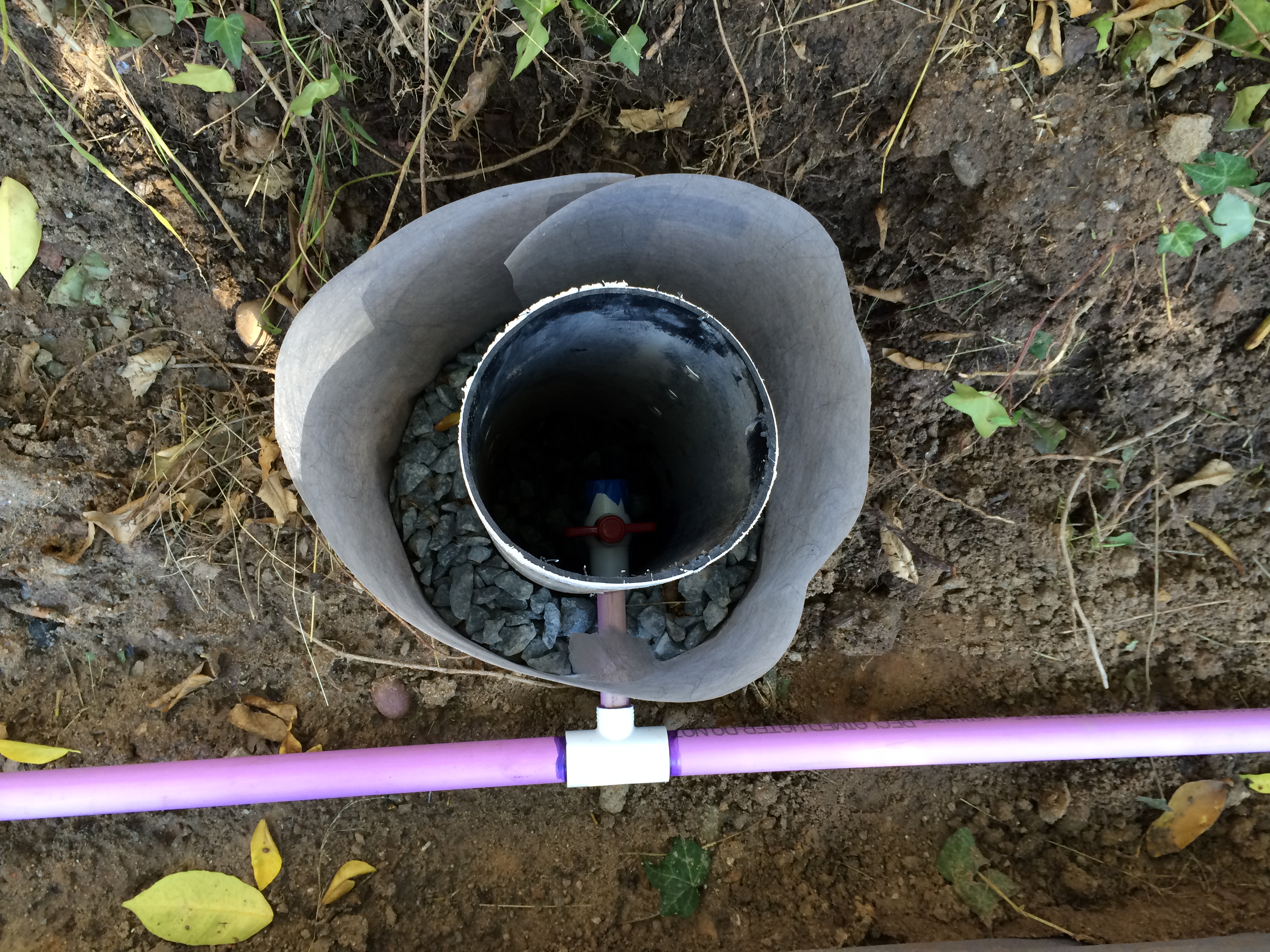
This shows the 1/2″ branch line coming off the 1″ main line and into a PVC ball valve. If you look closely, I put some masking tape over the open end of the valve for “Foreign Material Exclusion” (FME) purposes. I’m still going to be doing some additional backfill to finish things off, so I don’t want any unnecessary contamination entering the valve. If I can help it.

Piping is all installed. Note the little “white” pipe near the stake. This is what is called a “flex” pipe and it was invaluable in getting the pipe to fit through the tortuous path that was necessary. I highly recommend you include a few of these in your parts list for this type of project.

Another view of the pipe installation. Note how the pipe slopes away from the source (behind you).
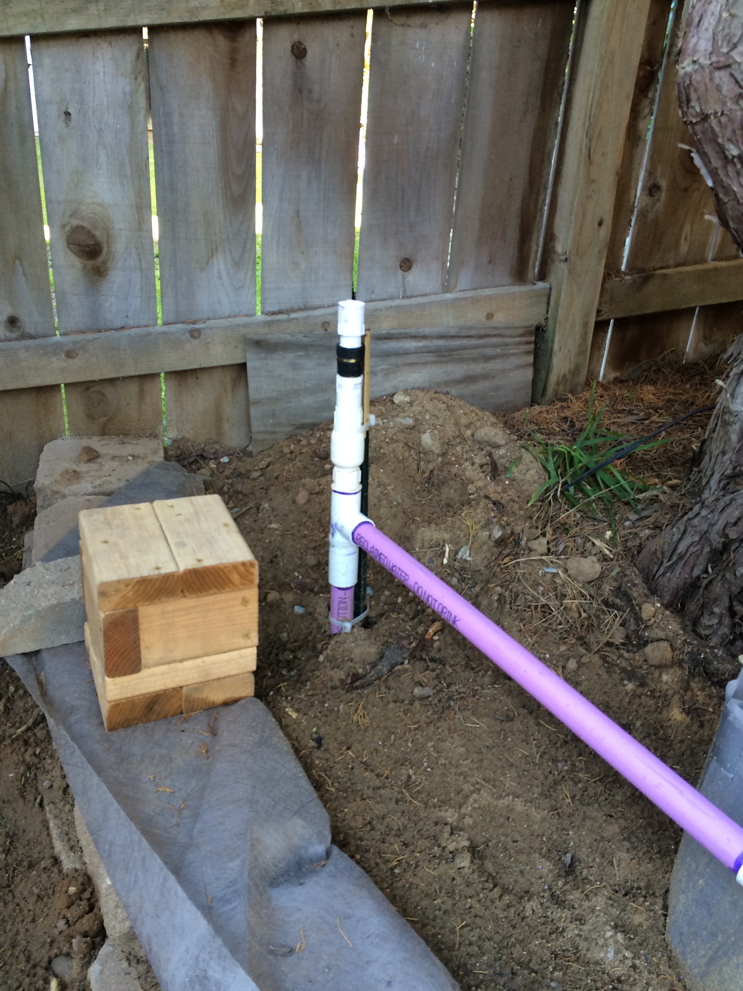
This shows the supply pipe coming up from behind the retaining wall. I have installed a check valve and hose fitting to the top to give me the ability to flush and/or perform supplemental irrigation with a garden hose. It is VERY IMPORTANT to only do this when necessary and to disconnect the garden hose when finished with the operation. You should also install a vacuum breaker at your hose bibb. There is some risk of getting soapy water into your plumbing if you leave the hose connected and don’t install that vacuum breaker, and you don’t want your crêpe Suzette tasting like Tide!
Now that the pipes are all installed, it’s time to get the rest of the backfill done. One slight problem remains, and that is how to re-insert the form into the fabric that you left hanging out there. It’s a pretty tight fit! The answer is to cut the form lengthwise almost all the way to the top, and then overlap the cut ends so that they fit into the fabric cylinder. These forms have some spring, so they will be able to pull the fabric taut again, and you can then proceed with backfilling and gravel filling as previously discussed. Here is an example of the finished product:

Ready for the rest of the backfill. Insert the cut form inside of the fabric and pull the fabric up as far as it will go. This will require some wiggling and jiggling, but it will get there.

Backfill around the form and fill with gravel up to the top of the standpipe. The measurements you made earlier allows you to use the top of the fabric as a guide for the height of the backfill and gravel fill.

Here is the drywell after the form is removed. It may take some effort because the form is pretty well sandwiched between the backfill and the gravel. I use a couple of pairs of pliers to get a good grip, and once the form was loose, it came right out. Looks really nice!
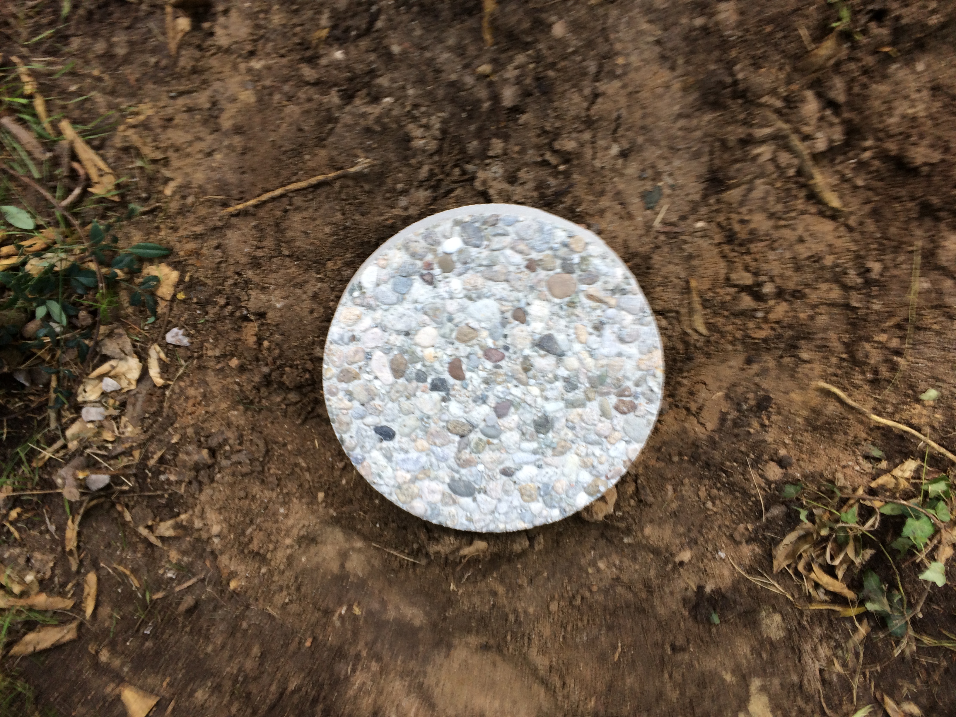
The concrete stepping stone is now in place. This prevents the detritus of the yard from entering the drywell, as well as provides an attractive cover. The average person admiring your yard will have no idea that you have a high-tech irrigation system buried below.
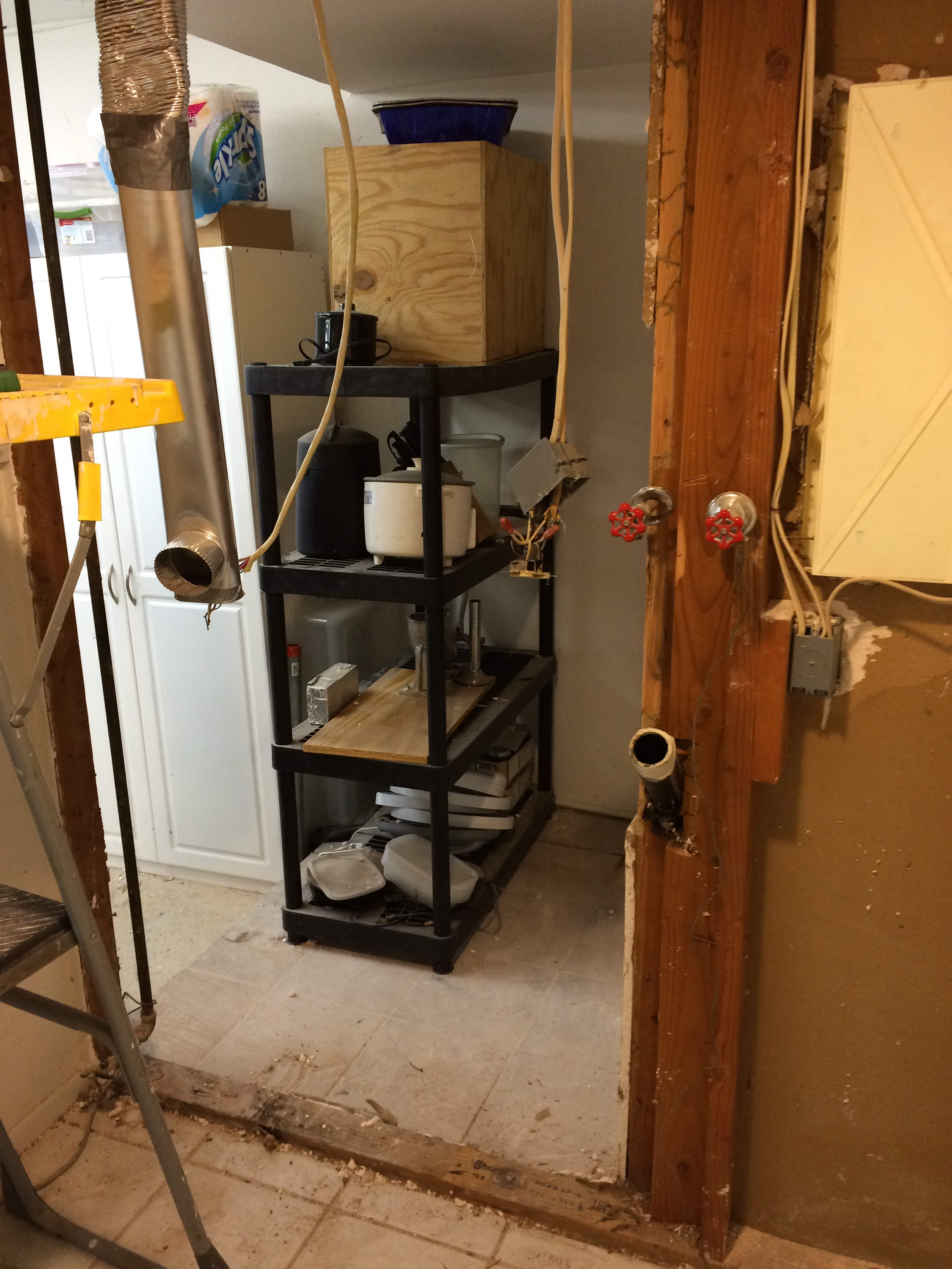
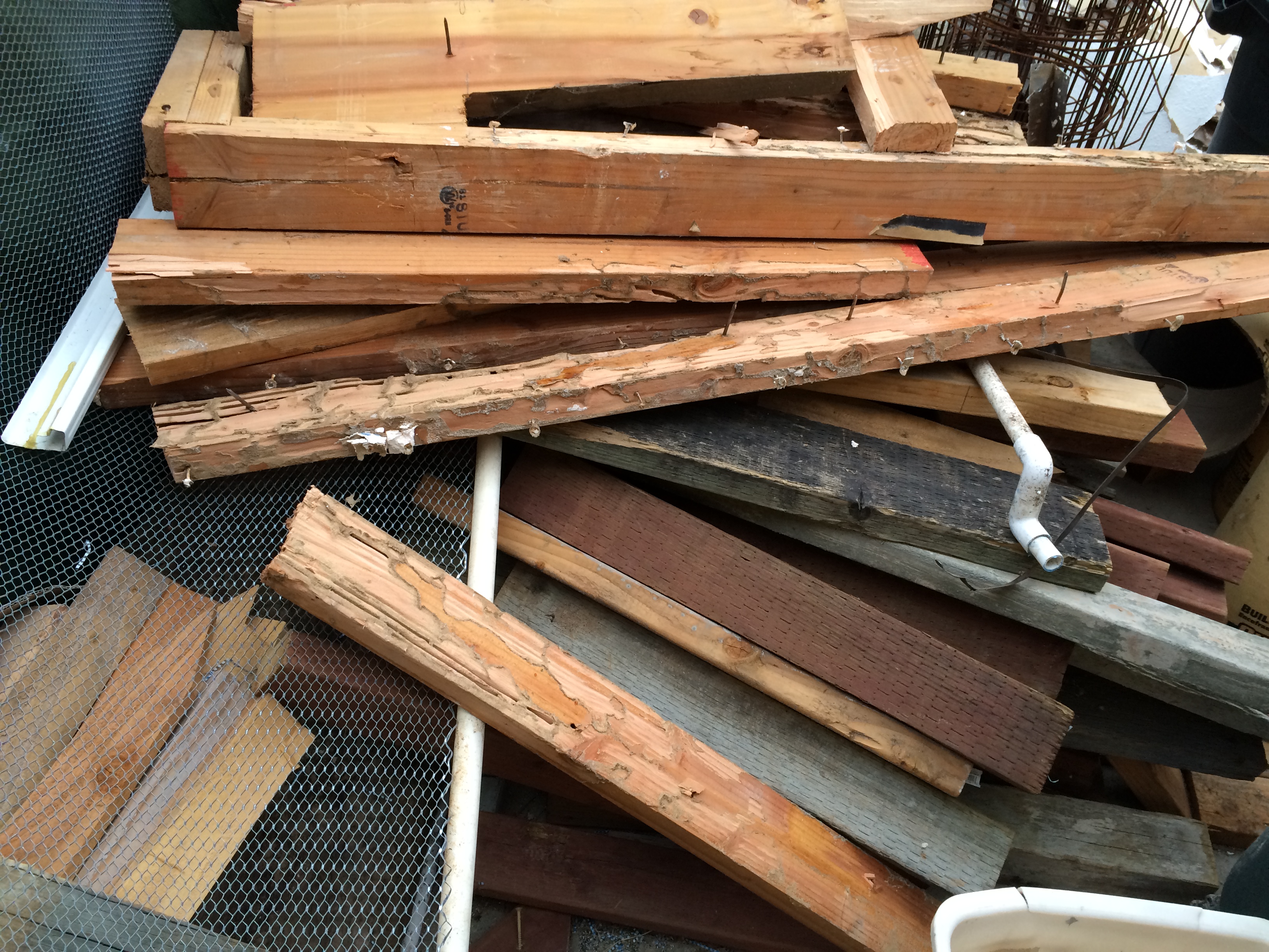
Now it’s on to getting the washer all hooked up and connecting the supply line from the washer to the pipes outdoors. As I alluded to above, one of the trickiest parts of this whole installation is the 3-way diverter valve. The first challenge is to find one. I tried the big box stores, speciality plumbing stores, and irrigation supply stores. I was going to go to a pool supply store because they make these valves for spas, but really, they’re typically too big, and therefore, too expensive. I was looking for a 1″ 3-way ball valve and I found what I was looking for on Amazon. (Click here for a link.) The next step was where, and in what orientation, to locate it. This can be challenging because (1) you have to know where your washing machine hose, washing machine drain line, and proposed route for your greywater line will be, and then orient the ports of the valve so you can accomplish the pipe hookup without too many bends. (2) you have to make sure you provide enough clearance to allow you to grip the handle and move the valve. (3) You’re typically dealing with very tight quarters because of the washing machine electrical outlet and the water supply valves and you have to avoid interference from all of that stuff. It helps immensely to dry-fit all of your fittings to make sure everything is going to line up later. Once you’ve got the location and orientation right, you have to figure out the mounting. This valve requires some torque to get it to move, so just putting in some drywall anchors and hoping things will work ain’t gonna cut it. If you don’t want to remove your drywall, then you could locate the studs behind the drywall and use pipe straps to secure the pipes that connect to the valve, but typically the studs will not be in a very convenient location to do this. An alternative is to get a piece of plywood that fits over the studs and screw it to the studs. You can paint it the same color as the wall, and it will blend in pretty well. After all, it’s a laundry room and the plywood will be obscured by the valve and associated piping. Plus, this gives you some freedom in choosing the final location of the valve. If you have the drywall down because you’re renovating or are building new construction, then you can install some horizontal blocking between the studs. I used this approach because I needed to replace the whole wall. That was because I found TERMITES when I was peeking behind the drywall to locate my plumbing lines. And I just had the house tented a year ago! Major bummer. But, it turns out that the plumbing and electrical crew that the original builder had done a real hack job on the original framing of this wall, so it was probably just as well that I replaced it with a proper retrofit. Here are some pictures of the 3-way valve mounting (and the termite damage).

This shows the 3-way valve all hooked up. I used hefty pipe straps around each of the PVC adapters that I screwed into the ports of the valve. This ain’t goin’ nowhere!
Hey, where did the wall go?
Here is the wall. What a mess!
Now for the hook-up. I was fortunate to be able to locate and align the 3-way valve so that I had a pretty clear shot to the existing sewer drain and to the outside. I originally wanted to run the line going to the outside through the wall, but the existing drain vent stack prevented that. So I opted just to run it outside the wall. This is not a big deal because the line will be concealed behind my freezer and all the other junk that I store in the little alcove that the line runs through. Hell, I won’t even paint it because I want to be a water conservation snob and show off that cool purple color. The only remaining problem was actually hooking it up to the washing machine. My washer came with a discharge hose, but try as I might, I found it extremely difficult to get a fitting that would provide a watertight seal under pressure. I guess that’s because a standard washer discharge hose is meant to go directly to your sewer drain and you want a loose-fitting to prevent the siphon effect. So it will be a non-standard size to purposely avoid a tight fit. This meant that I had to ferret around Home Depot and Lowe’s and screw around with various hose and fitting combinations until I found something that worked. Eventually, I found a replacement washer drainage hose that was flexible enough to insert a barbed 1″ PVC fitting. That meant pulling apart the washing machine to replace the hose. Actually it wasn’t that big of a deal because of the Internet. There are all sorts of appliance repair videos out there and these machines are designed to be easy to take apart, provided you know the tricks! At any rate, here are some pictures of the final hookup for the washing machine.
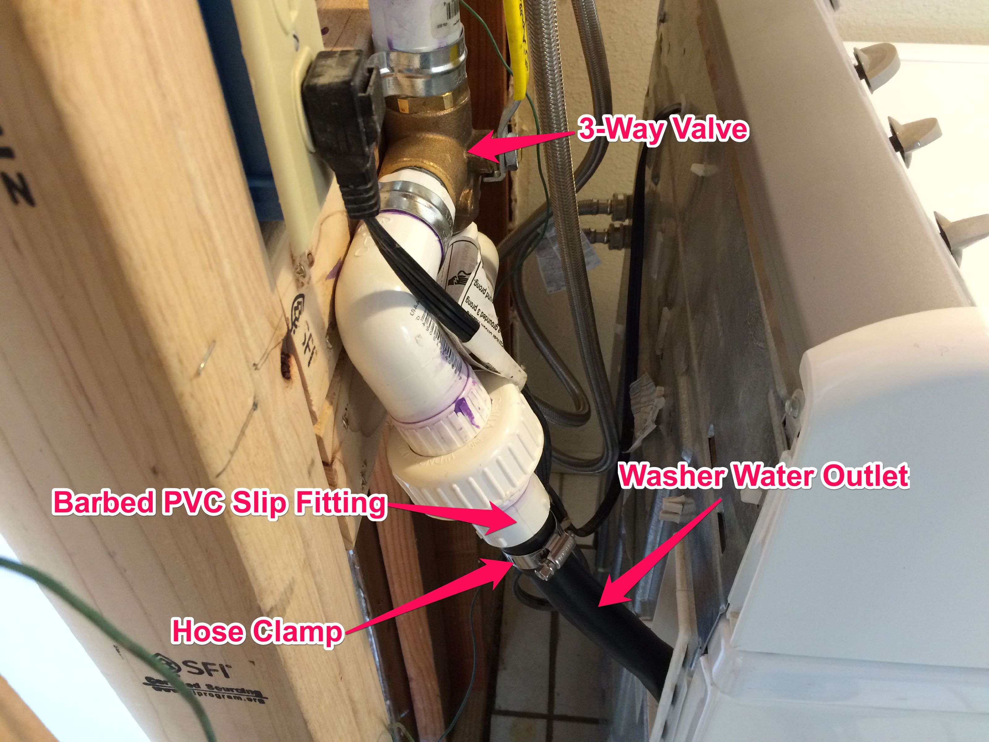
This shows how the washer outlet is properly secured to the inlet of the 3-way valve. It’s important to use a barbed fitting and hose clamp to prevent leaks.
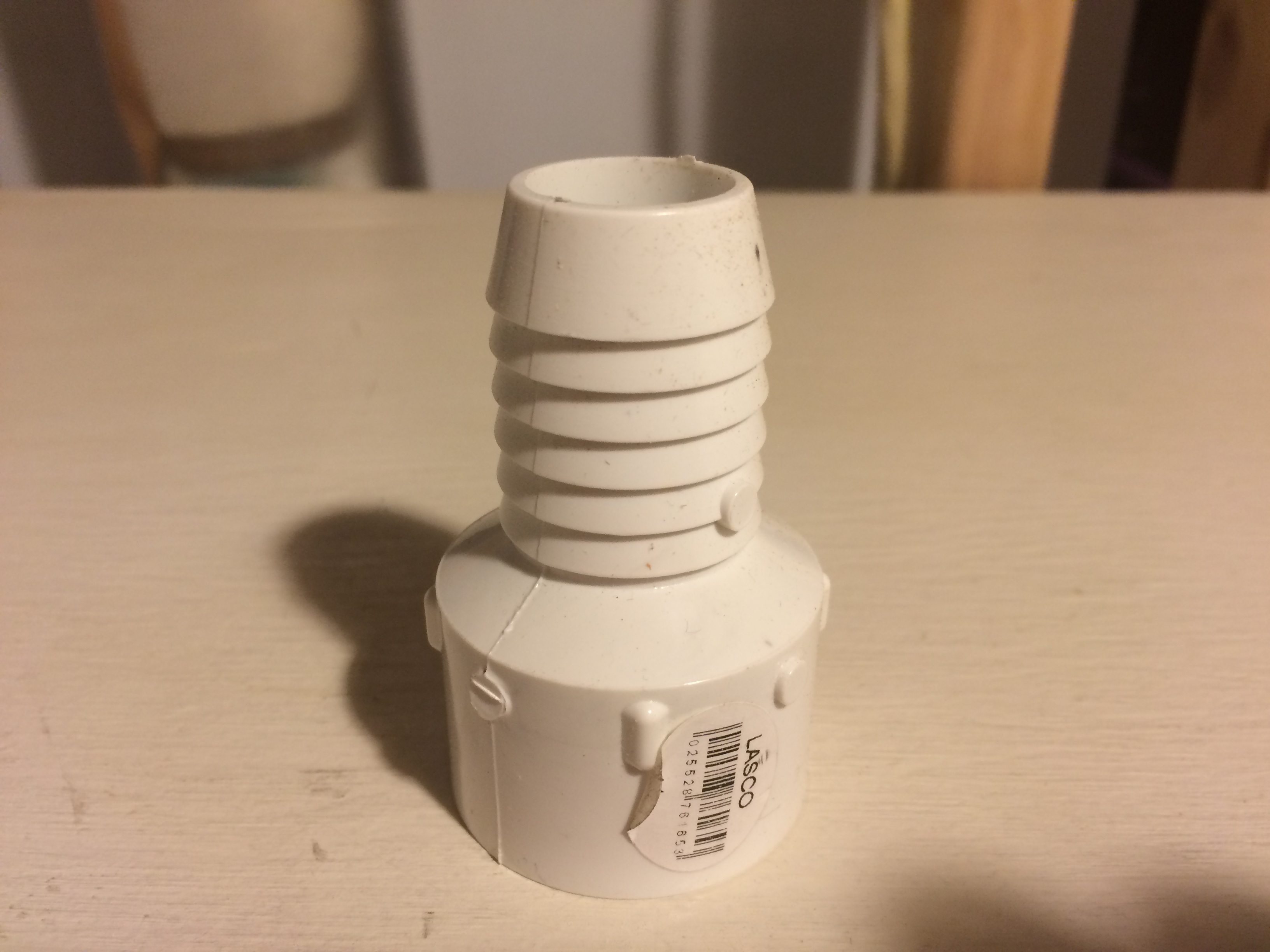
Here is a close-up of the PVC barbed fitting. Lowe’s carries these. Home Depot does not.
Lastly, I had to connect the greywater pipe from the washing machine to the standpipe I had previously installed (many months ago). I briefly mentioned above that the reason the washing machine discharge hose was intended to be a loose fit was to provide a siphon, or vacuum, break between the machine and the sewer line. Now I was defeating that safety feature by making a watertight seal between the new greywater distribution system. While the discharge going to the sewer still had an air gap (so no problem there), I needed to install a separate siphon break on the greywater irrigation supply line. This is actually quite a common plumbing fixture called an “air admittance valve” and they are readily available under the trade names of “Redi-Vent” (by Studor), and “Sure-Vent” (by Oatey). They are sized for a 1-1/2″ pipe, so you’ll have to get a reducer, but really no big deal. Here is a picture of my installation.

This is the vacuum breaker that you need to make sure that the greywater from your garden does not siphon back into your washing machine. Note the silicone seal where the pipe comes out of the wall.
Finally it was time to test! I went out to uncover all of the drywells and then removed the masking tape from each valve (to prevent contamination during the construction process) and opened each valve. I then filled up the washing machine with water and let her rip! The first load used to perform a system flush to make sure that any dirt in the system was fully flushed out of the pipes. I then did a couple of additional runs to adjust the streams coming into each drywell to be relatively equal. The only problem I had was that the last drywell was flowing too fast. That’s because I did not install a valve on it in order to make sure that the system had a reliable path to discharge water in case of a clog. I may rethink that because I do not believe my system is going to be as subject to clogging as the aforementioned bark mulch systems, but I might be wrong. Worst case is that the washing machine pump runs at shutoff head for a while before I notice it isn’t pumping, and then I go out to clear the lines. Here is a short video of the first run.
This was a long post, and I hope you liked it. I’m nearing the home stretch for the outside remodel, so I now turn my attention to the last big hardscape project: installation of the brick patio in back and the decomposed granite path in front.
Thanks for reading!
