Framing The Interior Walls

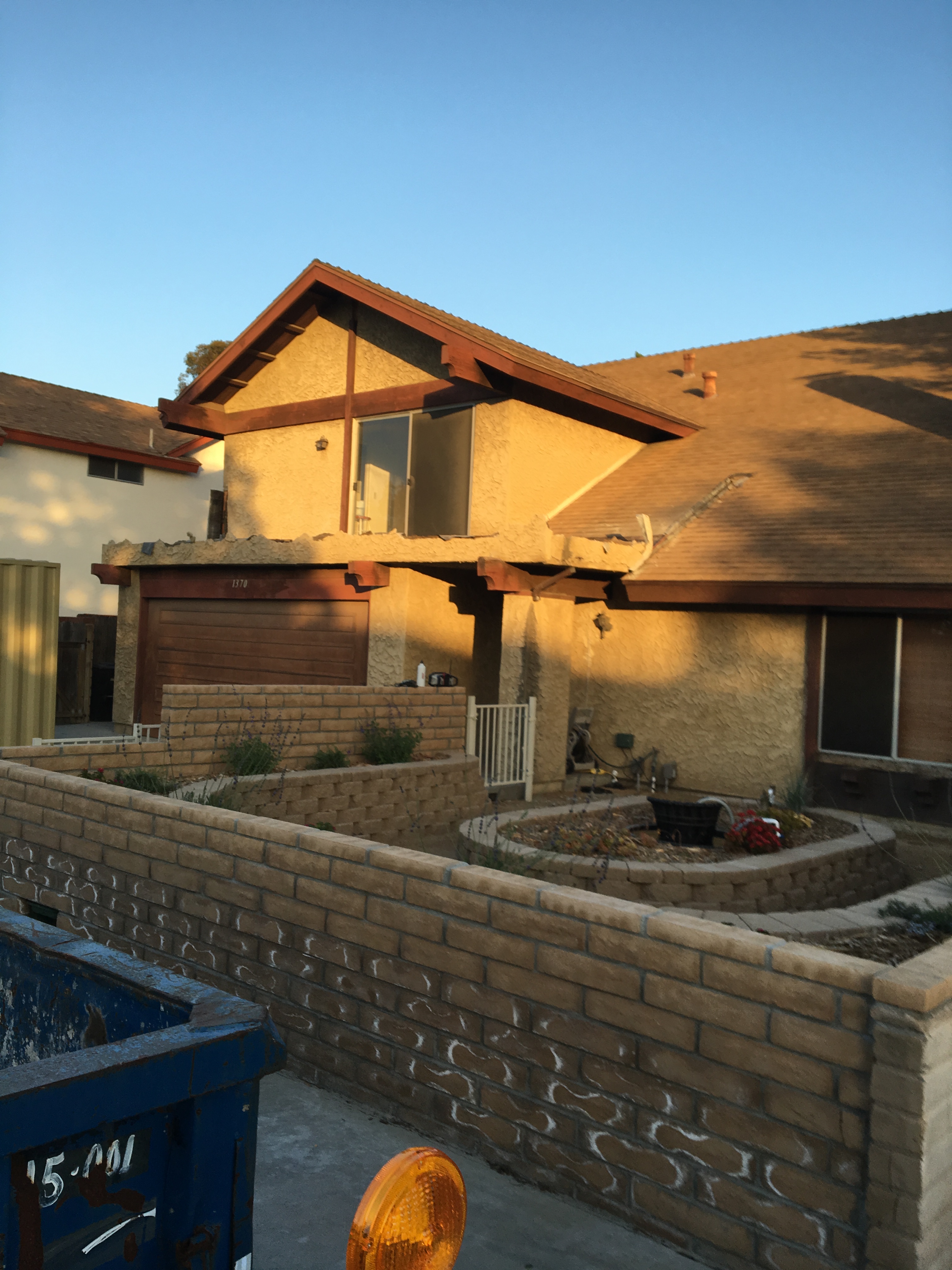
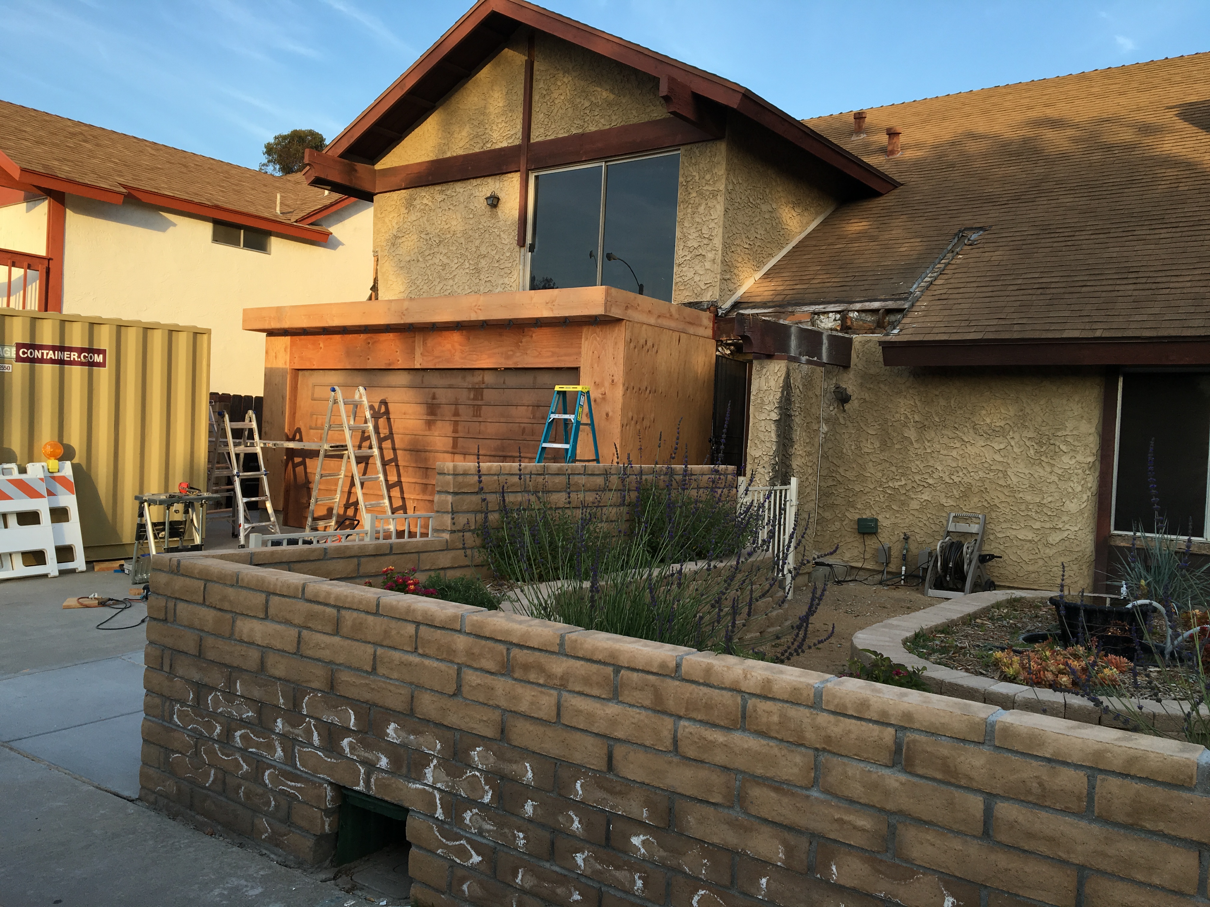
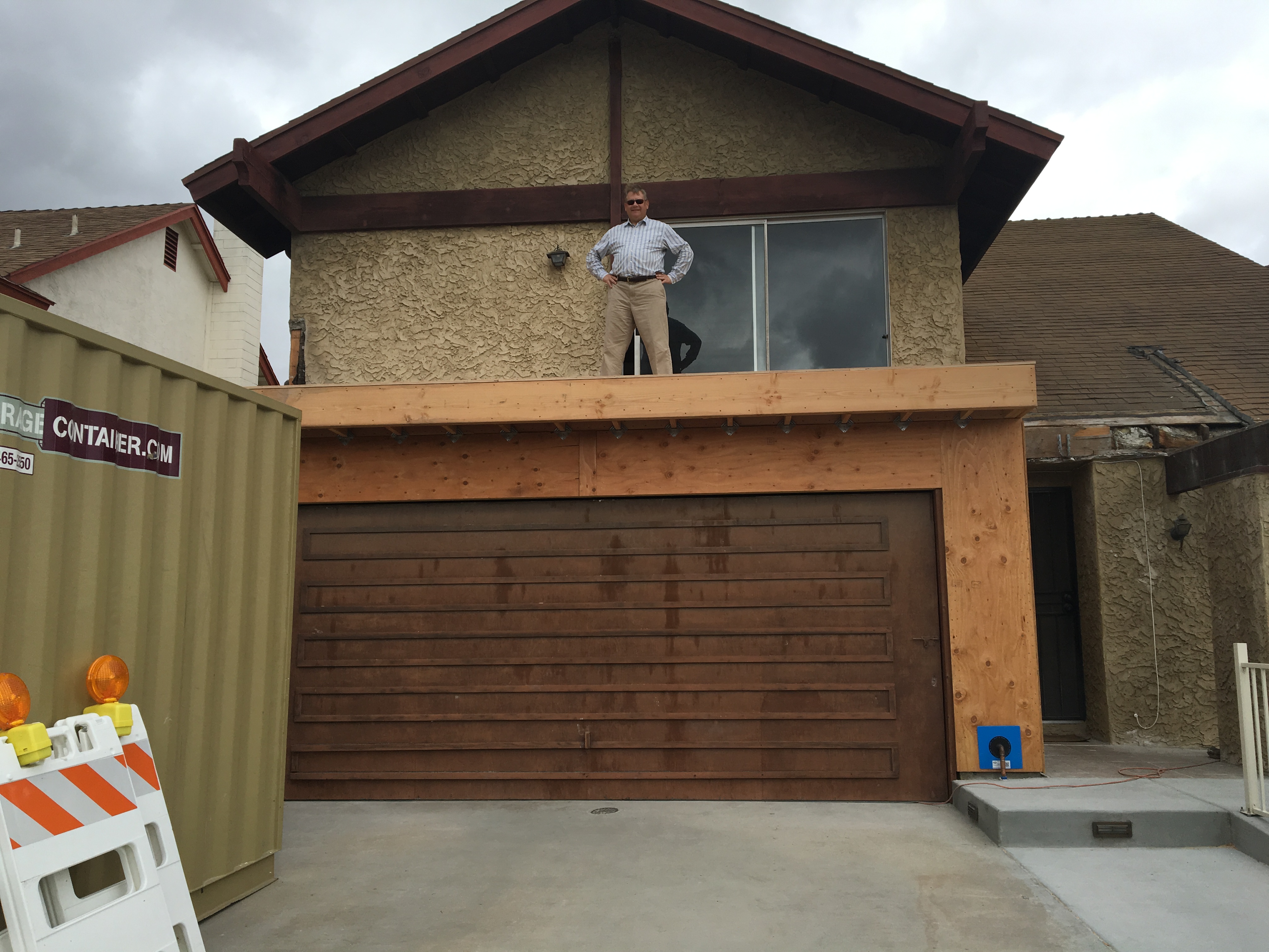
Now that the exterior part of the addition was complete, it was time to start work on the interior. The plans (that I designed and produced) had an “en-suite”, meaning an adjoining bathroom and other facilities. As a matter of fact, the design reflected my predilection for the “process” of getting ready for the day: do your business, brush your teeth and shave, shower, and then dress. Well, that’s my order. My wife’s order is not the same, so that meant that if we had a scheduling conflict, one could be in private for the “business end”, and the other could take care of the rest. But I digress….

At any rate, I had to construct the framework which meant erecting a wall, and then putting in false ceilings and compartments to define the elements of the space. I had to make the wall that separated the en-suite from the rest of the bedroom, and a couple of smaller walls that separated the toilet area from the shower and dressing areas. These two smaller walls also had to accommodate pocket doors. The framing for these walls was pretty standard (except for the pocket doors — more on that later), but I had to do some detail work to make sure that I had all the correct structural components figured out.

Interior wall construction is similar to exterior wall construction but if it’s a non-load bearing wall, you don’t have the same requirements, meaning that you don’t have to use structural grade lumber, and don’t have to have a bunch of connectors. However, because lumber and drywall are produced to standard dimensions, the rules on top plates, sole plates, and stud spacing generally apply. Other than applying exterior sheathing, the techniques for construction are exactly the same.

Step One: Measure and Mark. The best starting point for wall construction is to lay out the wall on the floor. Professional carpenters do this for all the walls at once because it both speeds the construction process, and  but more importantly, it ensures accuracy and minimizes mistakes because you can see if everything fits together when you transfer all of the plan dimensions to full scale all at once. Not that there were any mistakes in the plans, mind you….(!)

(A) Locate the interior wall from a convenient reference. I used the existing exterior wall and the interior wall end that I had to marry up with.

Tools required for layout. If you’re doing this solo, then you need a handful of finishing nails and a hammer to hold the end of your chalk line (which I have in my belt, but neglected to photograph).

Plan for the wall. I drew this custom from my model. Typically you’ll just have a plan (overhead) view and have to figure out all of the vertical stuff, and I could have probably just done a quick hand drawing, but I’m also the designer, draftsman, and engineer, so I can do it how I want.

Location of sole plate from exterior wall framing.

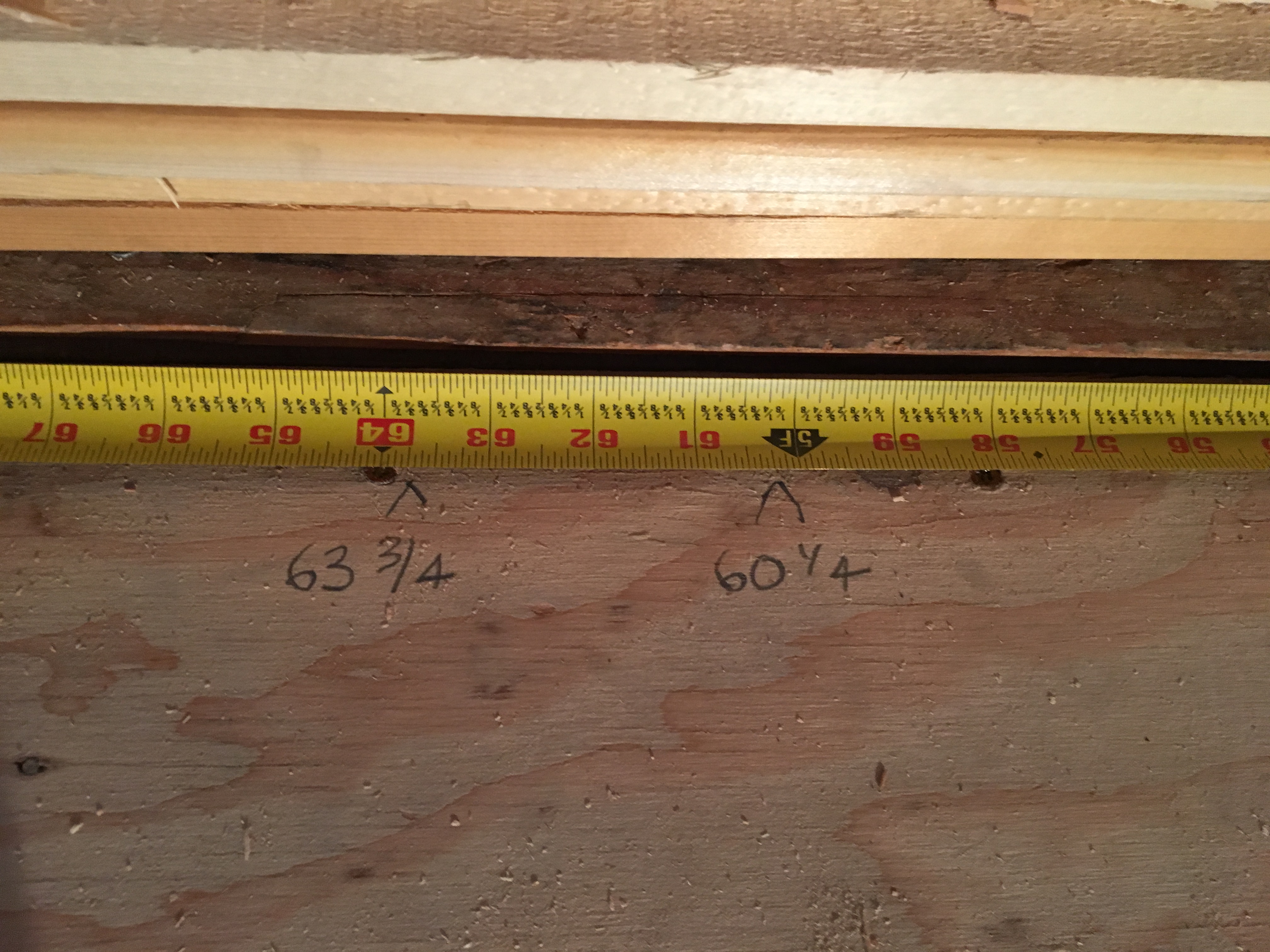
(B) Check for square. Never assume that any previous work is perfect. Anything you build will have

errors that slowly build up and must be corrected for at each step.

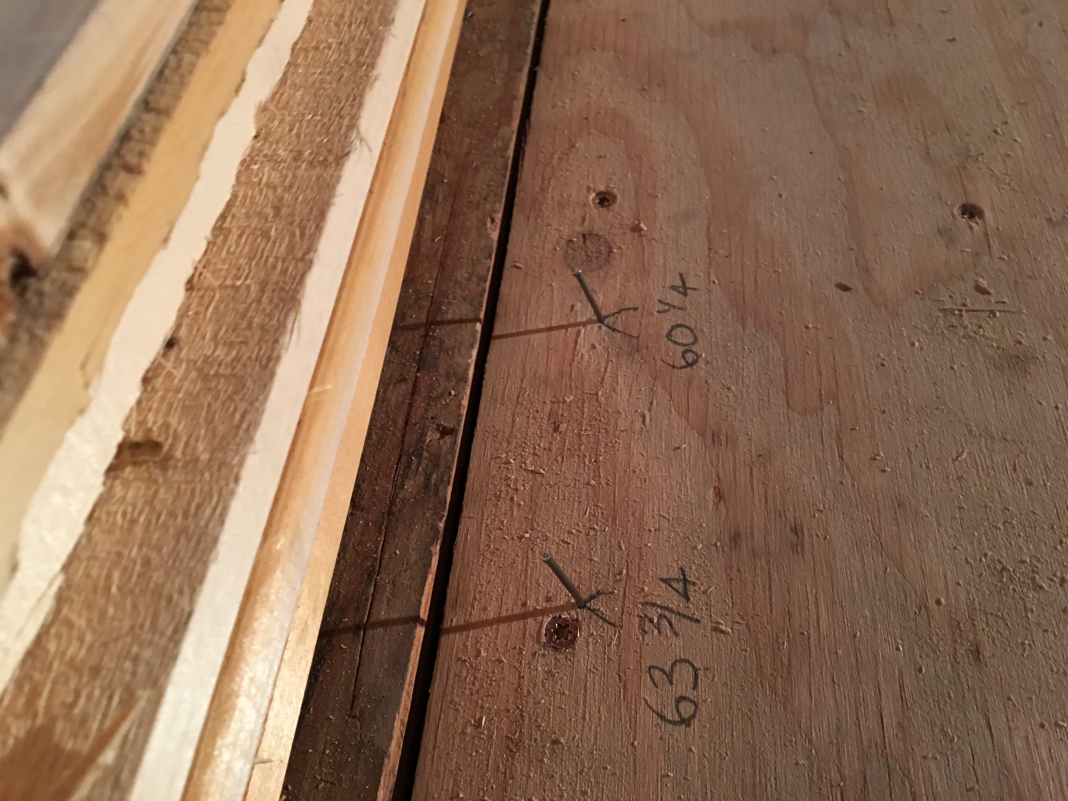
Check marks to make sure they’re square before you snap the chalk lines. This is 63 3/4″ from the exterior wall.

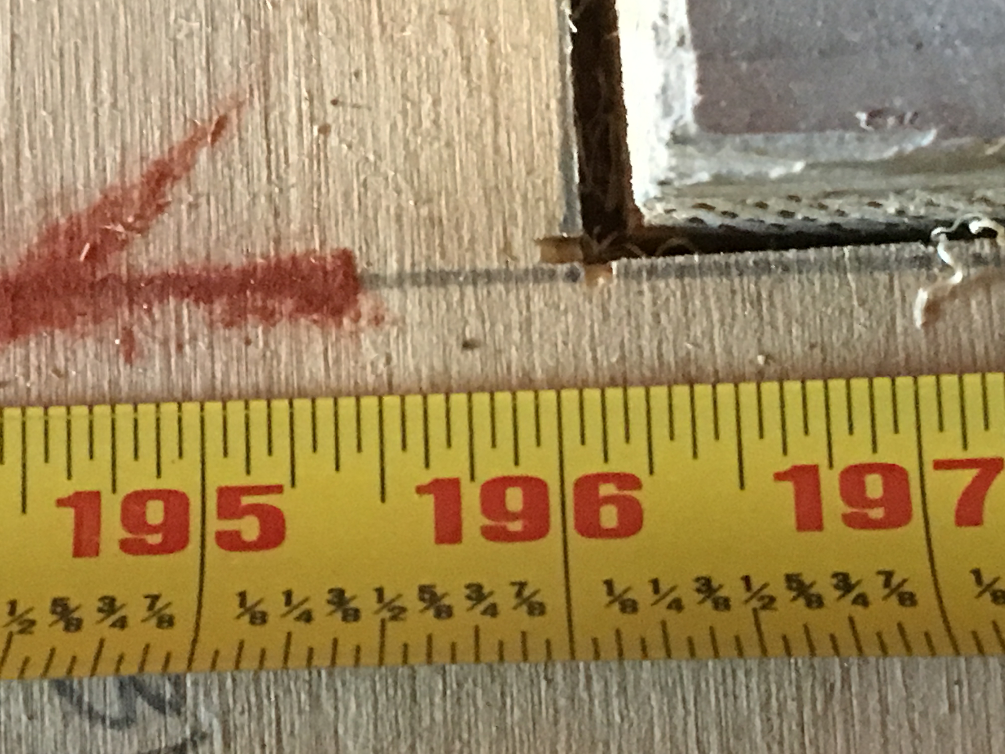
Measure a convenient distance along the exterior wall.

Calculate the hypotenuse of the triangle using the good old Pythagorean Theorem which you learned in middle school (you did, right?).

The moment of truth. Dead on.

Once square is confirmed, locate the other end of the wall out from the reference (exterior wall). Wall baseline measurements in place with nails for holding the chalk line. Marks are also made at the other end of the wall (not shown here).

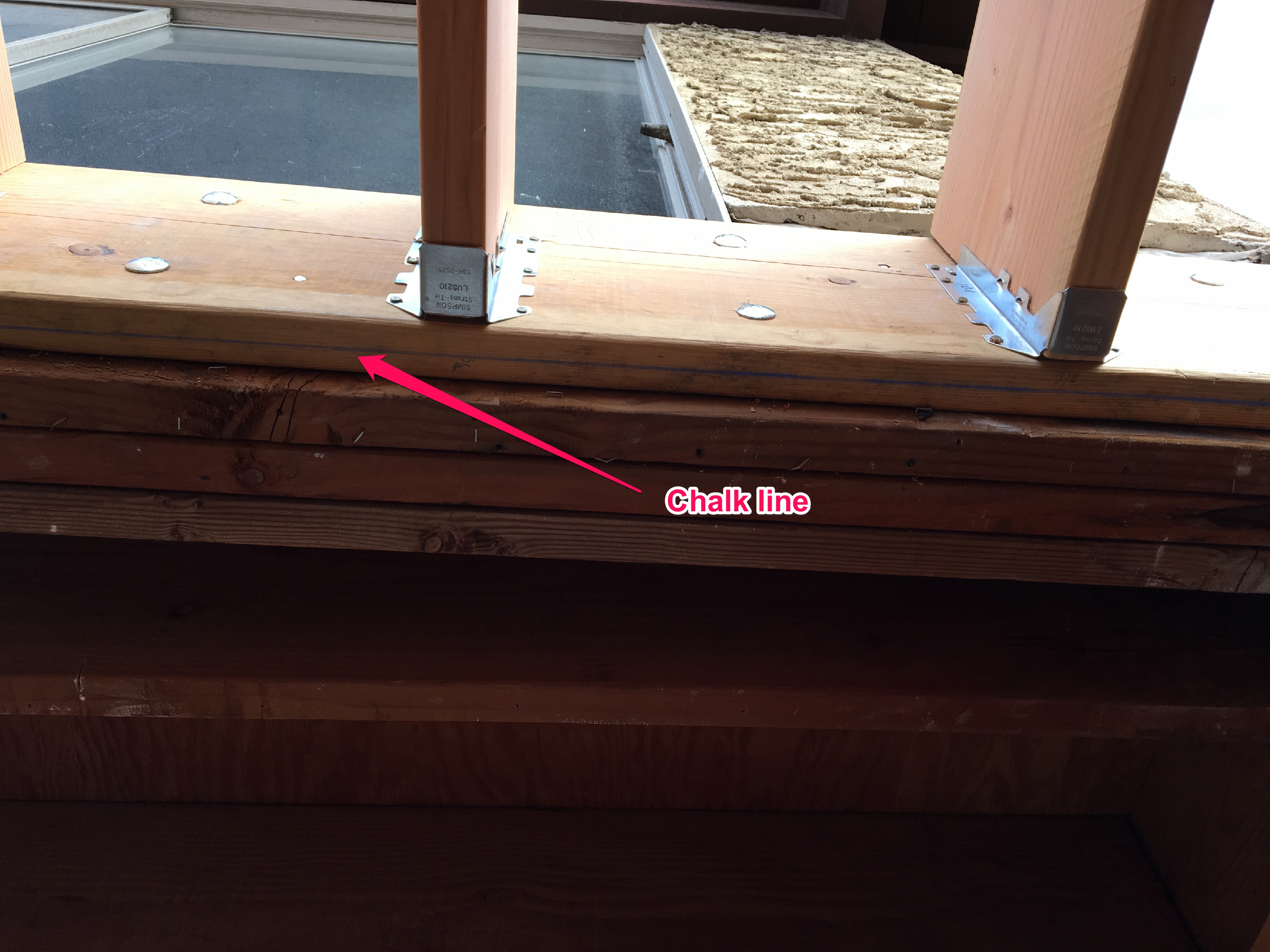
(C) Snap baselines for the sole plate.

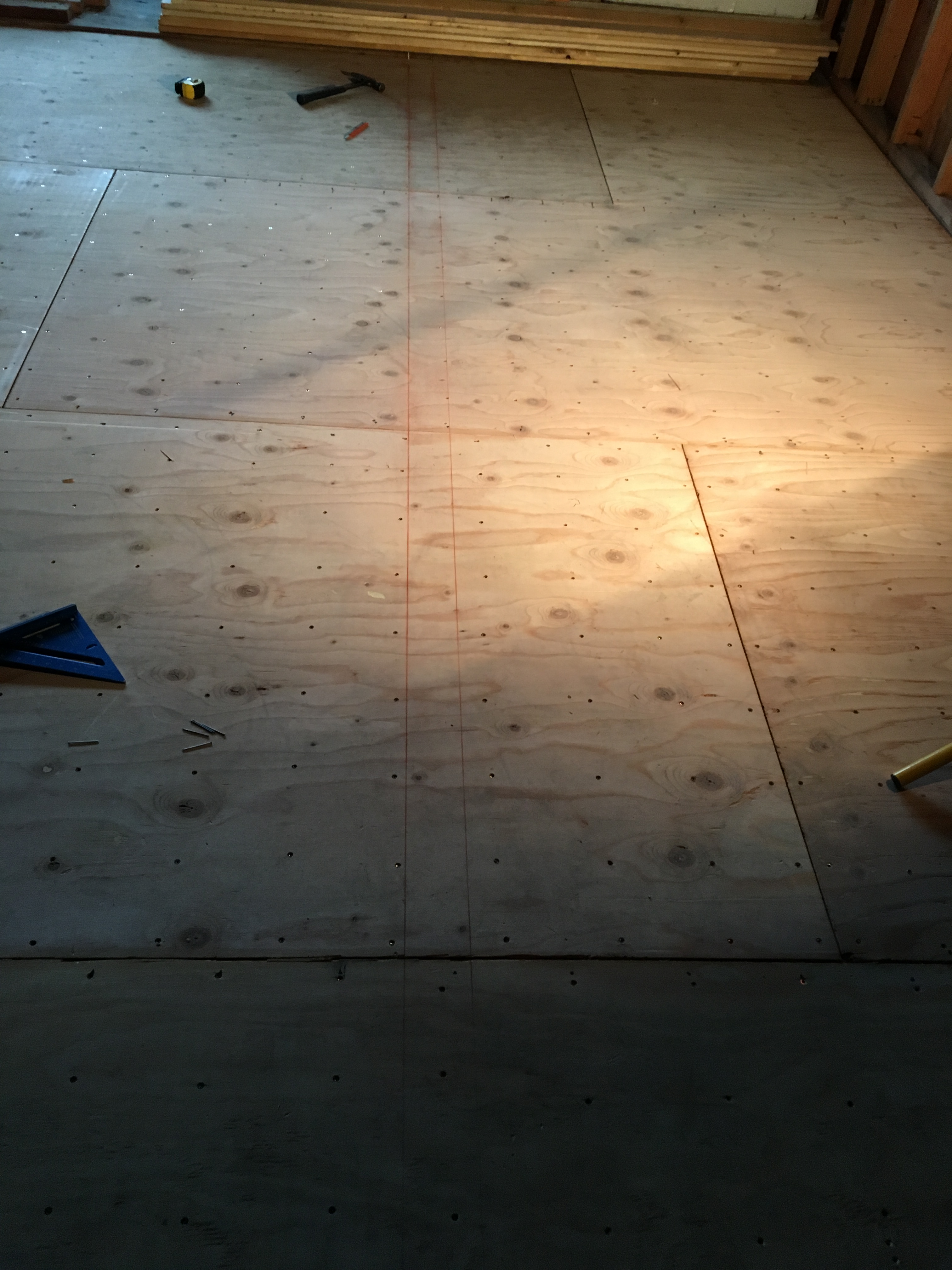
Wall baselines snapped.

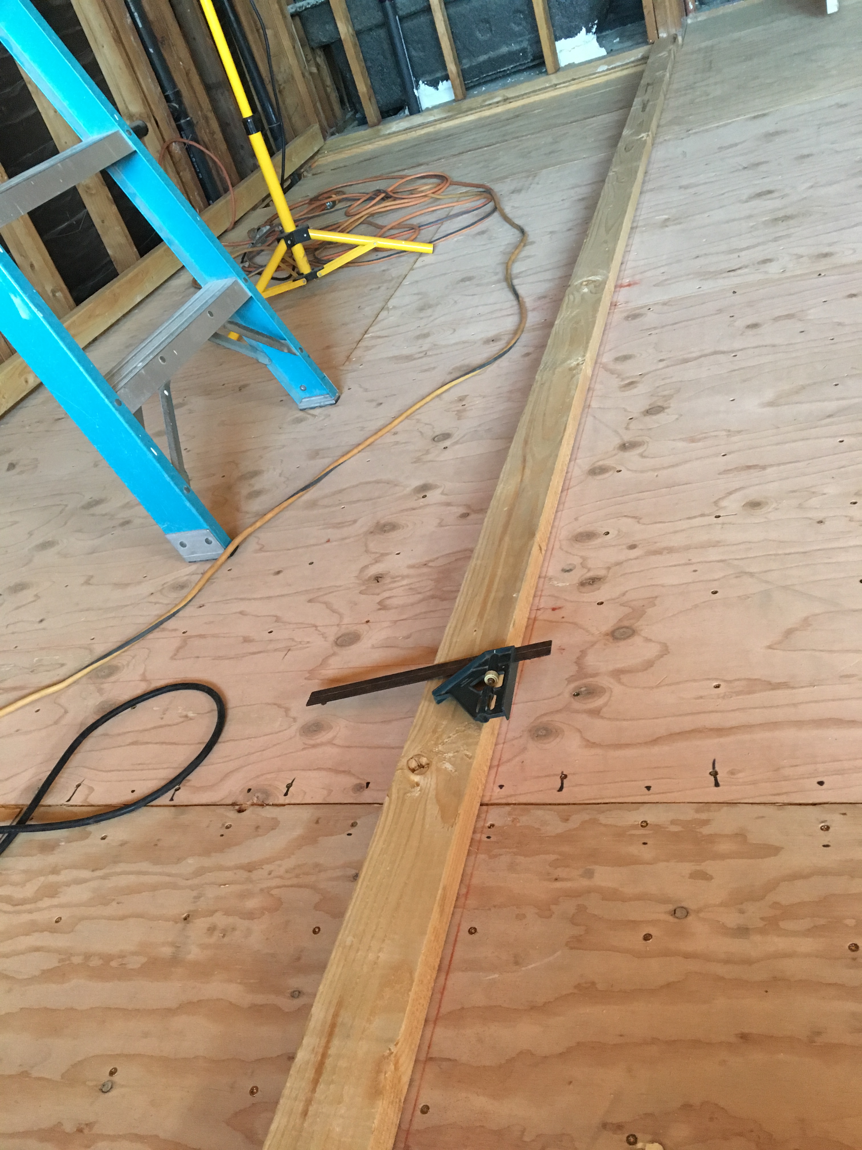
(D) Mark the openings and intersecting walls. I needed to mark the entrance to the bathroom and the two intersecting walls that defined the toilet area. I ended up changing where the toilet walls were located to match where the drain was, and also decided to change the door swing to make it more ergonomic. Once you lay things out in full scale, you will find you will need to adjust. The plans are never (exactly) right!

The red marks indicate changing the location of the partition walls to match where the rough plumbing for the toilet came in.


I decided to change the door swing to better accommodate ergonomics for entry and exit from the bathroom.

Step Two: Make a kit. Once the lines for the sole plates are marked out with the door openings and intersecting walls, it’s time to start marking out lumber and cutting. The key to framing any wall is to carefully mark out where all of the studs/jacks/cripples will be on the sole plate, and then transfer those marks directly to the top plate. This ensures that the ends of each stud/jack/cripple will be vertically aligned, making the wall relatively easy to square up and put in place.

(A) Cut the plates to size.

16′ lumber ready for marking. I will only use two pieces for the wall plates (sole and top) and the third will be a header for the false ceiling inside the wall.


Measuring out the length of the sole plate.

I put the measurement on the lumber so I won’t forget!

(B) Transfer the marks from the floor layout to the sole plate.

Sole plate on baselines, ready for marking.

Marking where the header of the toilet enclosure wall will go. The marks are transferred directly from the layout on the floor.

(C) Transfer the marks to the top plate.

Sole plate and top plate clamped up for marking. You want to mark both at the same time for accuracy and efficiency.

Marking cripple studs on top plate. These will be transferred to the door header when framing up.

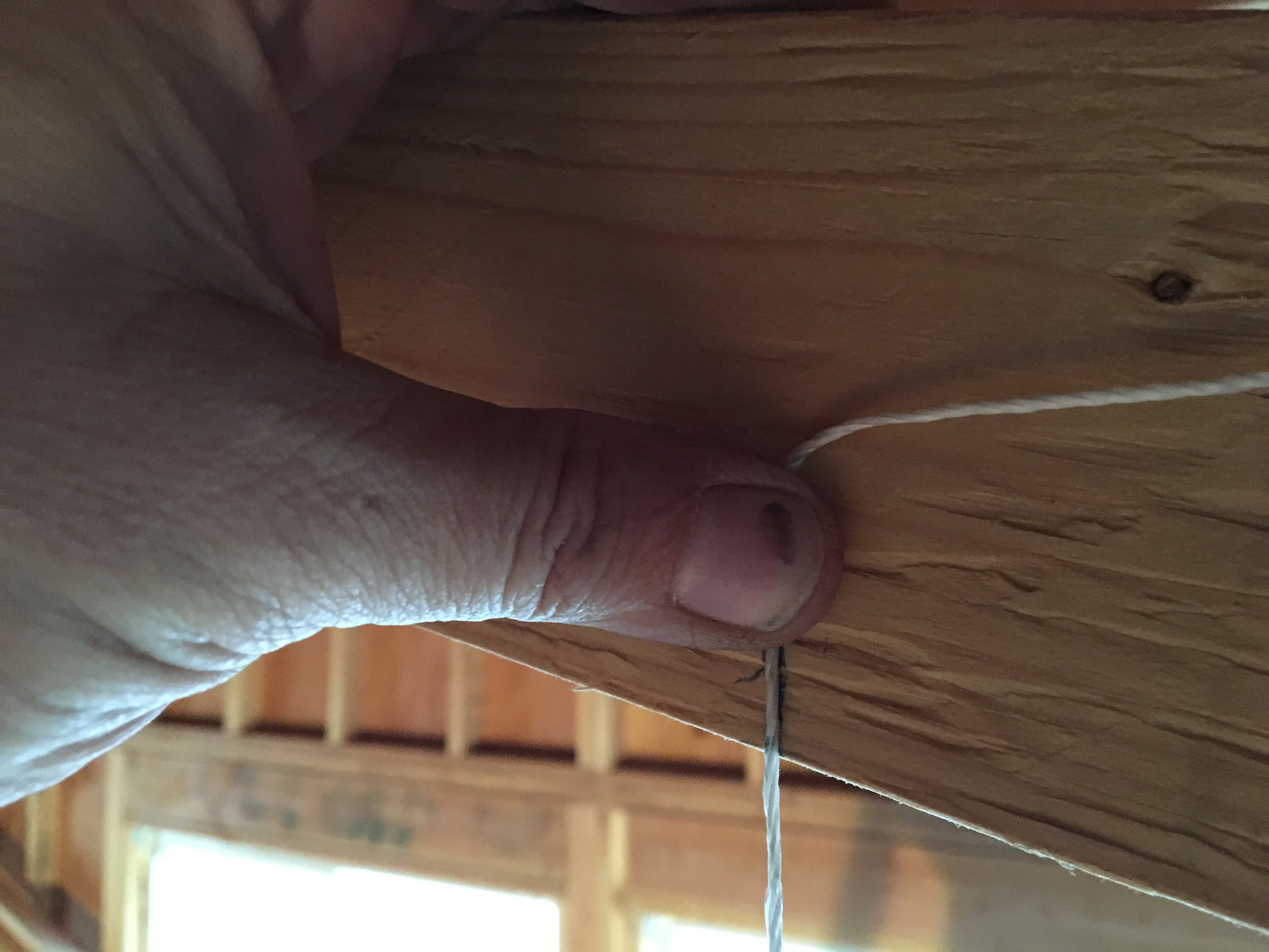
If you want a 16 oc spacing, you have to offset the first one from the end by 3/4″.

(D) Make a cut list. This is done by methodically going through each mark on your top and bottom plates and figuring out how many studs (vertical pieces of lumber) you need and of what kind. There are four kinds of studs:  Common (or just “studs”), Cripple, Jack, and King. Common studs are what you’ll have the most of. They are the height of the finished wall MINUS the thickness of the sole and top plates. For an interior wall with just one of each, that’s wall height -3″. With a double top plate, it’s wall height – 4-1/2″. In my case, the wall was going to meet the undersides of the trusses, which were angled to form the cathedral ceiling. So I had to use a plumb bob to find where the inside edge of the wall would touch the truss and measure from there.

Plumb bob lining up the edge of the wall to the truss. It’s actually pointing to the wrong line in this picture, (the correct line is the one on the lower right) but you get the idea.

Marking the bottom of the truss.

Mark on bottom of truss directly above the inner edge of the wall (i.e., the face of the wall towards the bathroom). Finish nail is in place to snap a chalk line.

Chalk line snapped on bottom of trusses to align the wall when it’s raised.

Back to the types of studs. Cripple studs are short studs that connect the tops/bottoms of wall openings to the sole or top plates. So, you’ll have a few of these wherever you have a door or window. In this case, I had a door and needed to place cripple studs between the door header and the top plate. Jack and King studs are what form the sides of the wall openings (windows/doors). The jack stud provides vertical support for the header while the king stud sits right next to the jack stud and provides stability to the header. The king stud is the same length as the other “common” studs but has a different name due to its function and location within the framing.

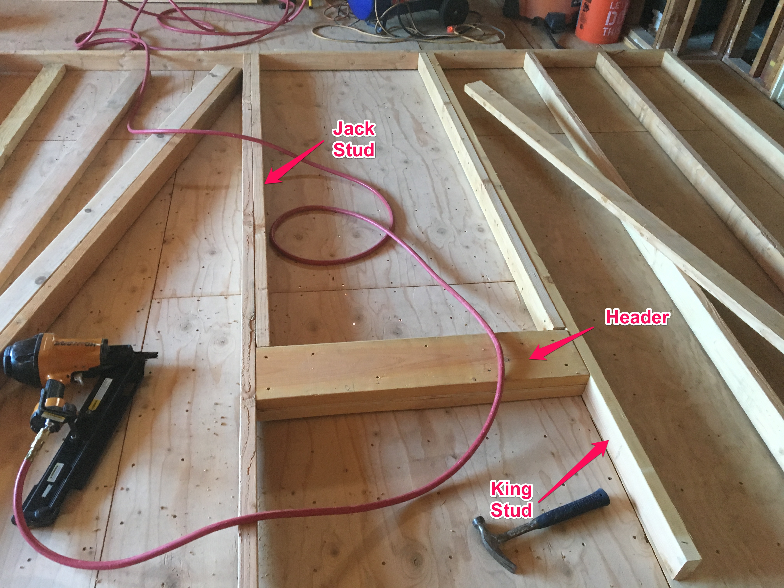
Door framing showing relationships between framing members. The cripple studs go above the header (where the hammer is). Note that the bottom of the door has the sole plate going right across. This will remain until after the wall is lifted and secured in place to make the wall assembly stiffer and easier to lift. It’s a simple matter to cut this out with a handsaw after the wall is up.

Once all of the various studs have been counted (and double counted), I put them into a table called a “cut list” to make sure that I didn’t leave anything out and that I had all of my measurements correct. I also put in the materials for the headers and the 4×4 header supports for the two smaller walls for the toilet area. Take some time to double check your work here because if you make a mistake and cut all your studs 4″ too short, you’ll have a lot of extra firewood and an unexpected trip to Home Depot.

Cut list. Makes it easy to get an assembly line going and helps keep track of where all of your parts are.

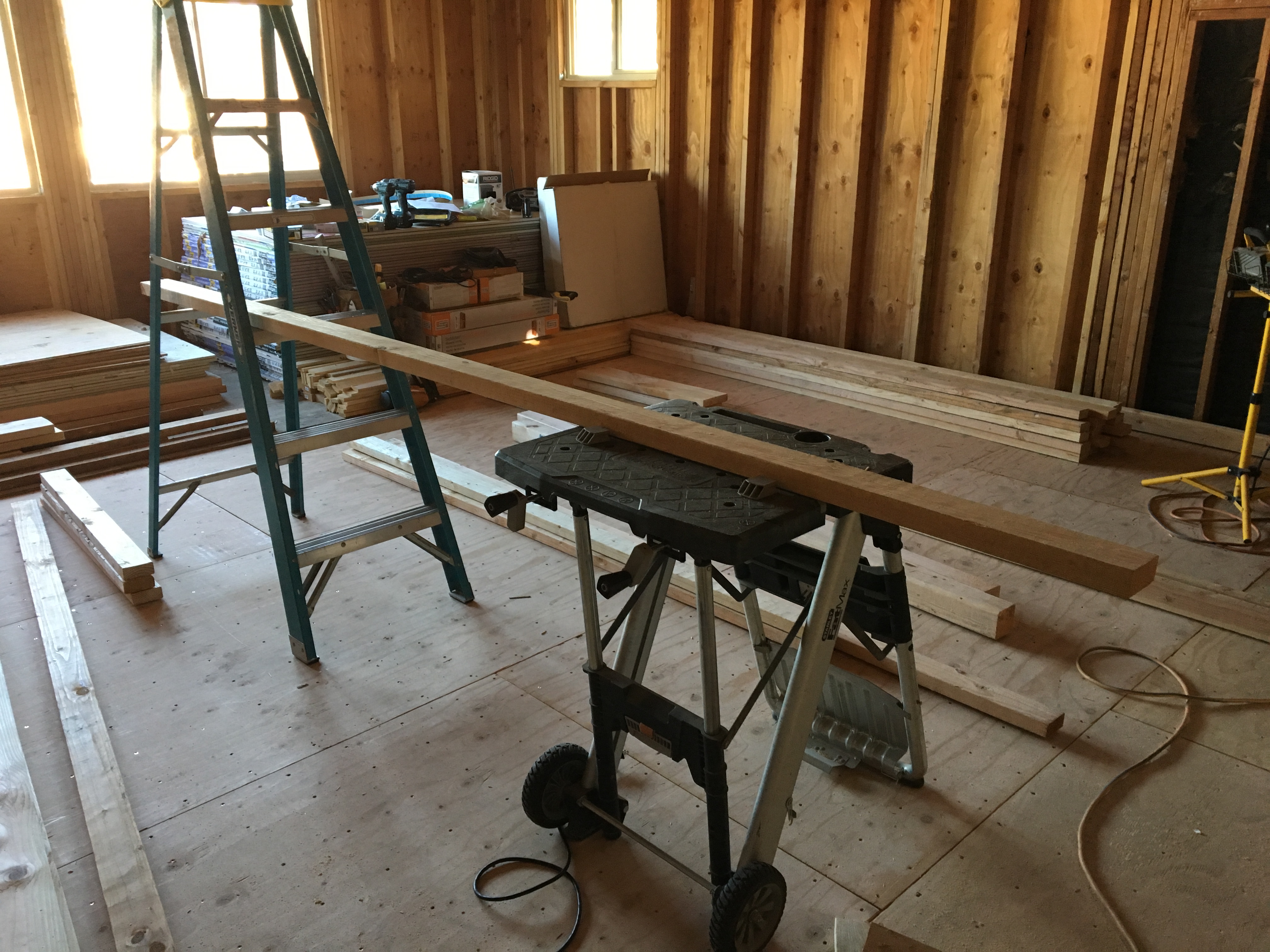
Cutting station. I couldn’t get my fancy (and too heavy) miter saw stand up here, so I improvised. Worked great!

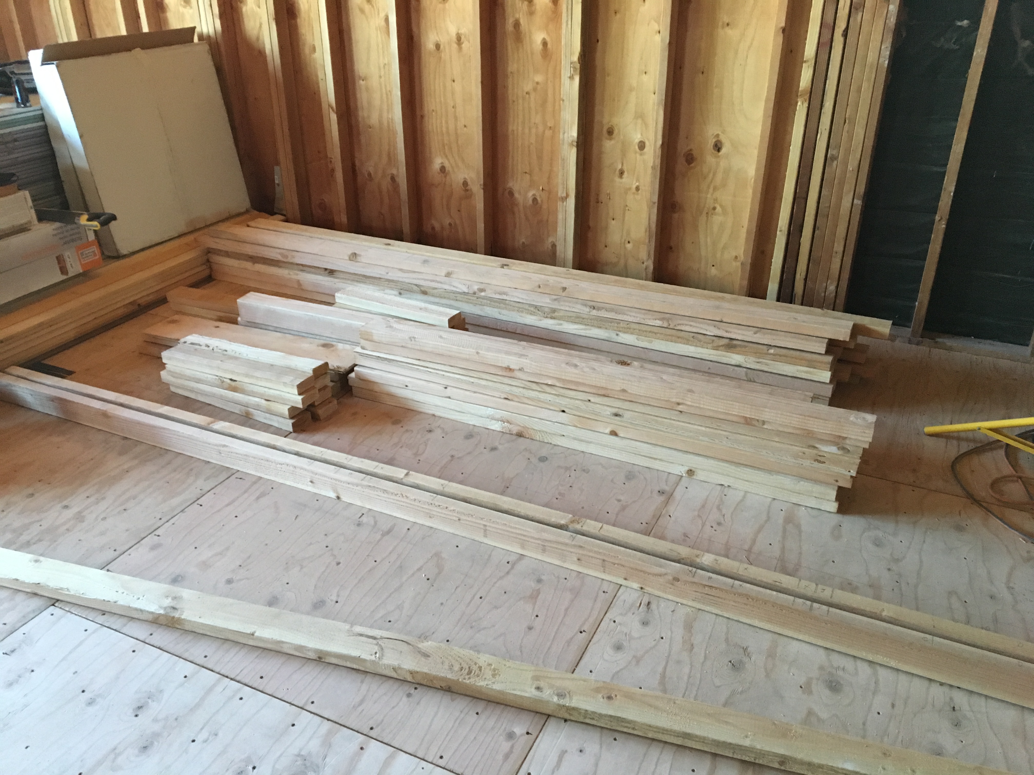
All studs, cripples, jack studs, plates and headers stacked and ready to roll!

Step Three: Assemble the kit. This should be the easy part, right? Just separate your top and bottom plates, scatter your studs and arrange your headers and start banging away!

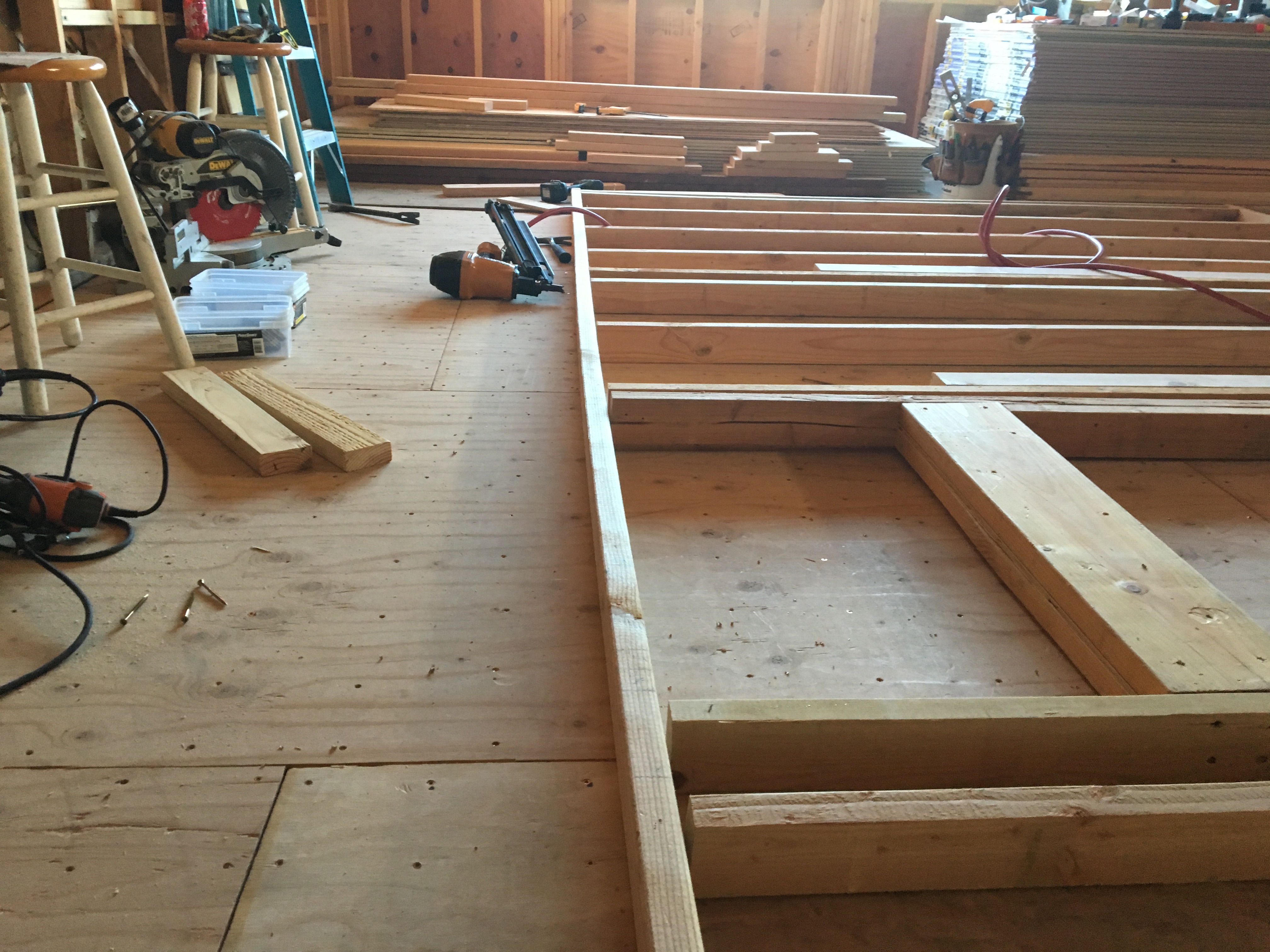
Kit components aligned on the floor, ready for assembly.

Well, not so fast. There are a few subtleties that bear mention when putting this thing together. First and foremost, you need to plan for a logical assembly sequence so that you avoid having to nail components awkwardly, or worse, have to disassemble a part because you couldn’t get to it. For this wall, I made several sub-assemblies so that I could accurately nail them together without interference from adjoining components. These sub-assemblies included the header, jack and king studs for the door, and header supports for the two walls separating the toilet area.

King and jack studs for door are pre-assembled. It’s a lot easier to face nail these two together when sitting flat then it is to try to bang it together when on its side and you have a floor and other studs to deal with.

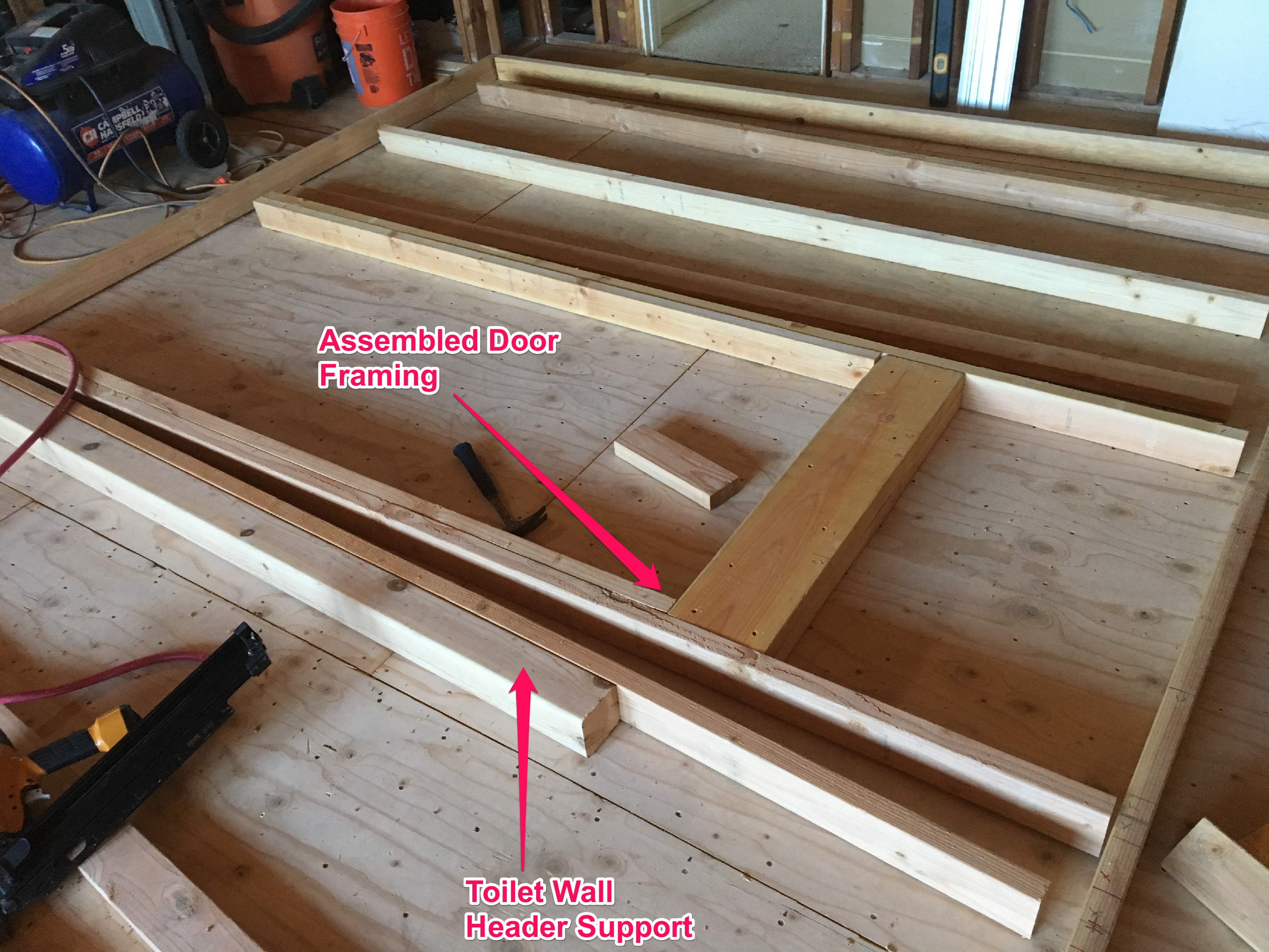
Door framing subassembly with header, king, and jack studs. Also a partial assembly for the toilet wall header support (the one with the 4×4). I only nailed one king stud so that I could easily slide the header onto the support once the wall was up. I would then be able to nail the second king stud in place on the other side. This is a good example of thinking several steps ahead to avoid unpleasant problems in the future.

A good place to start is at one of the corners. I started with the sole plate.

Sole plate complete.

The other issue that you have to deal with are imperfections, both with your materials for the wall and the surrounding structures where the wall will go. Wood is rarely perfect. Some lumber can be badly warped. In some cases, you can take the worst pieces and use those for cutoffs, like cripple studs, where the warp won’t matter as much. Also, you can use warped lumber for the inner studs, where it doesn’t matter very much. Save your straightest pieces for the ends and the door framing, where that alignment matters most. You can also use leverage and beaters (sledgehammers) to “persuade” recalcitrant pieces of lumber into place.

Because of variations in the height of the floor (long story) I needed to put shims underneath some of the studs so they would be aligned with the plates.

Using a “cheater bar” to untwist lumber for nailing. I attached a 2×4 to the inside of the stud and then pulled like hell while I nailed the end to the top plate. I then removed the cheater bar.

Securing the top plate.

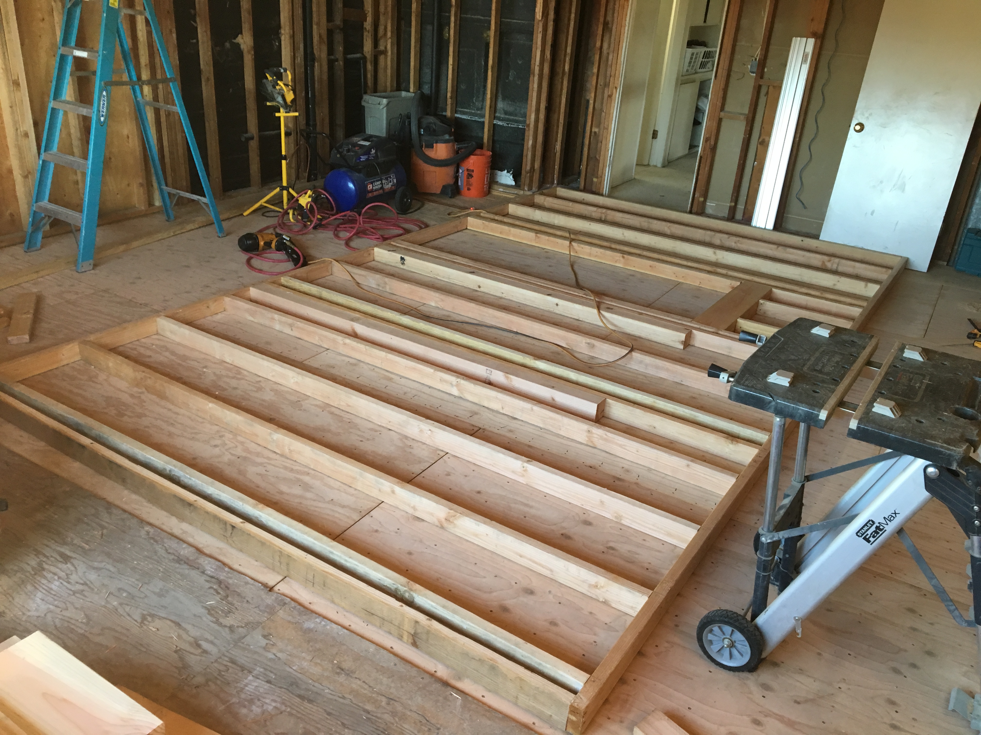
Wall complete and ready to raise!

Step 4: Raise the wall. Now it was finally time to raise the wall. Because it was inside the structure, I couldn’t use the wall jacks that I used for the exterior walls because the lumber used for the jacks would not fit under the ceiling. So I had to do this the “old fashioned” way with some helpers. The interior wall framing is lighter because it has no sheathing, and is also “flexible” meaning that I did not bother to perfectly square it up before I raised it. This is because it was going to fit between the floor below, lower truss chords above, and abut against an adjacent wall. So long as I had marks on the floor for the sole plate and marks on the truss chords for the top plate, and these two were plumb to each other, I could be reasonably certain that the wall would be plumb and in alignment with the rest of the framing.

Wall raised and in place.

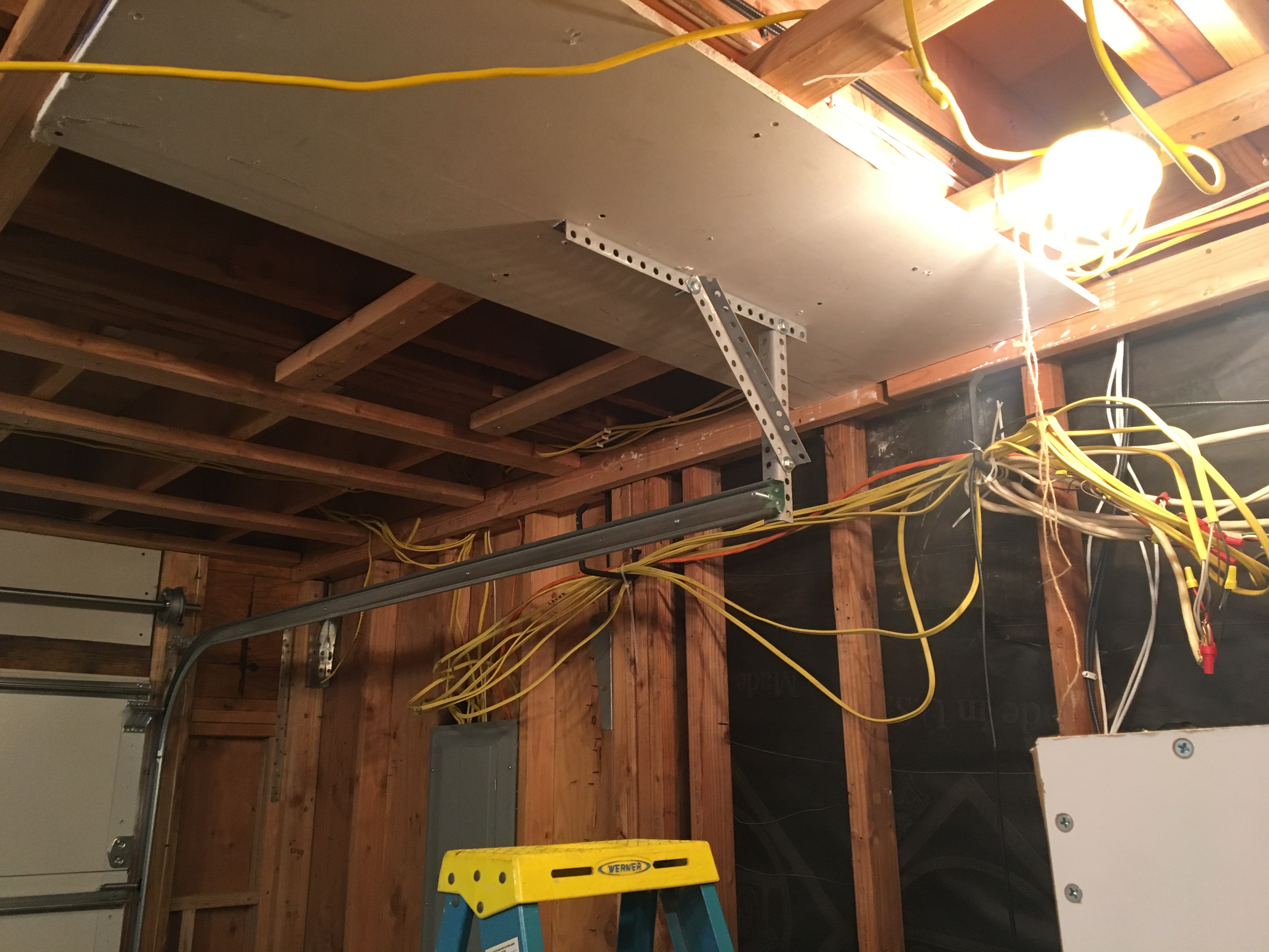
Because the main wall intersected the slope of the cathedral ceiling, I had to make a few accommodations. Specifically I had to install blocking on the top plate between the trusses to lock in the top of the wall. See the following picture of the false ceiling.

Step 5: Finish the interior details: Lastly, I had to construct a false ceiling on the other side of the wall and add a couple of partitions. Since I wanted the toilet to be separate and isolated when necessary, I had to put in walls that accommodated pocket doors. Pocket doors require an entirely different framing system. There are many types of systems that use basic materials to do the framing, but from a DIY standpoint, I found it more expedient to just buy a kit. The instructions were pretty straightforward, and as long as you’re accurate with the measurements, it’s largely foolproof.

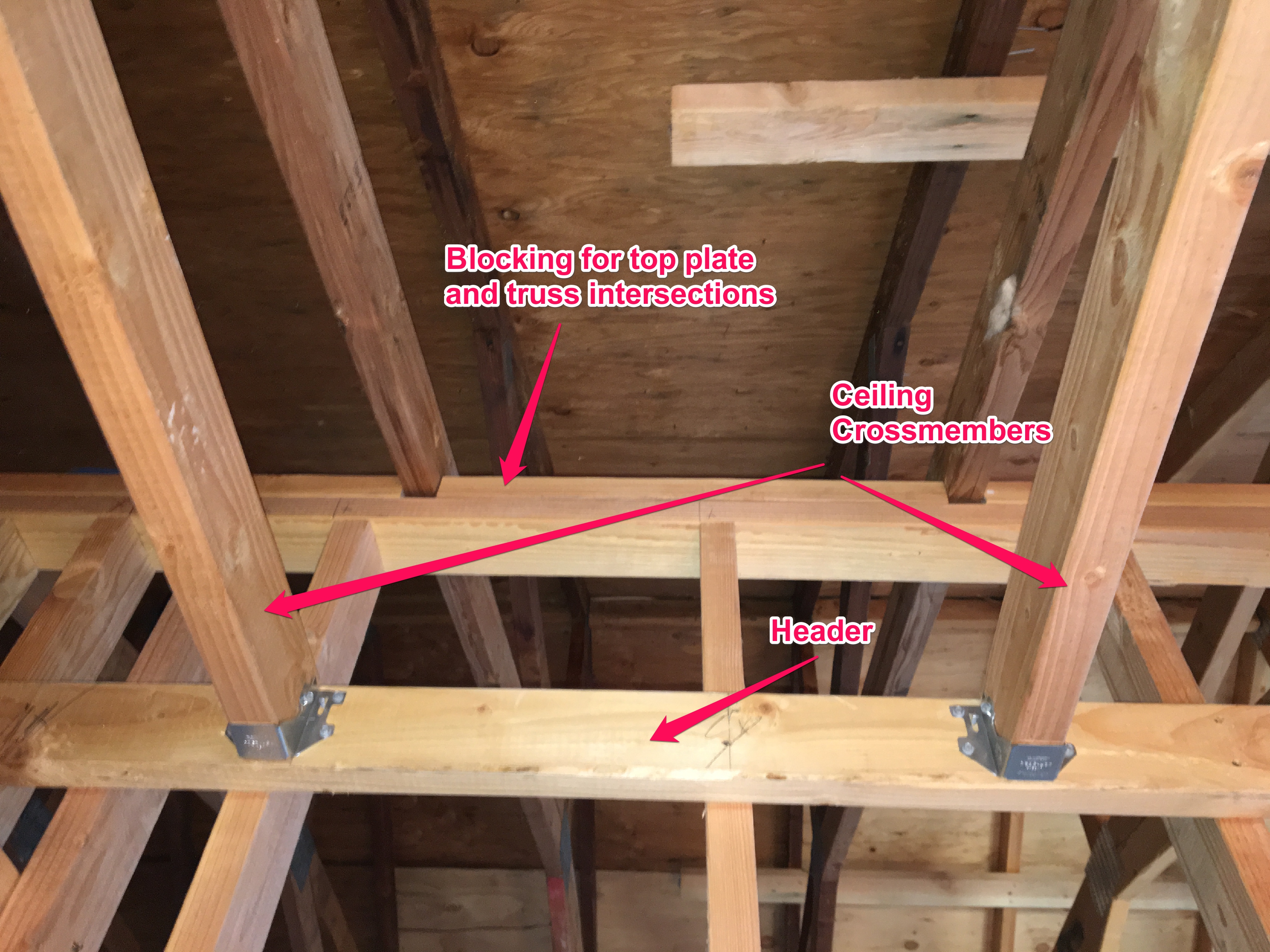
False ceiling assembly detail showing the header and the false ceiling cross members.

Hangers for pocket doors installed. The headers for the doors will rest on these and when the door kits are installed, these will form the walls for the toilet area.

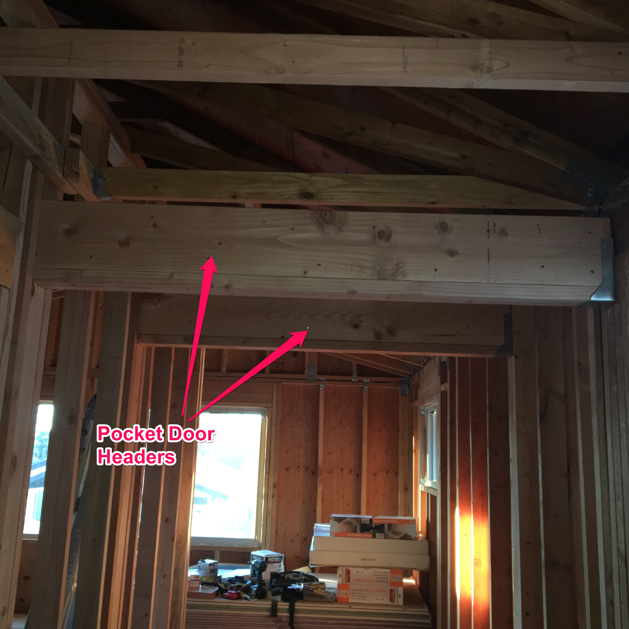
Pocket door headers installed.

Pocket Door Kit Instructions. This is the easiest solution.

Pocket door installed. I couldn’t find a picture of the framework (!)

The last thing I did was to cut out that piece of sole plate that was interfering with the door. If you recall, I constructed the wall with a continuous sole plate to help hold it together when the wall was raised. Now that the wall framework was finished, it was time to clean up that little detail.

Door opening with sole plate in place. I’m going to take care of that presently.

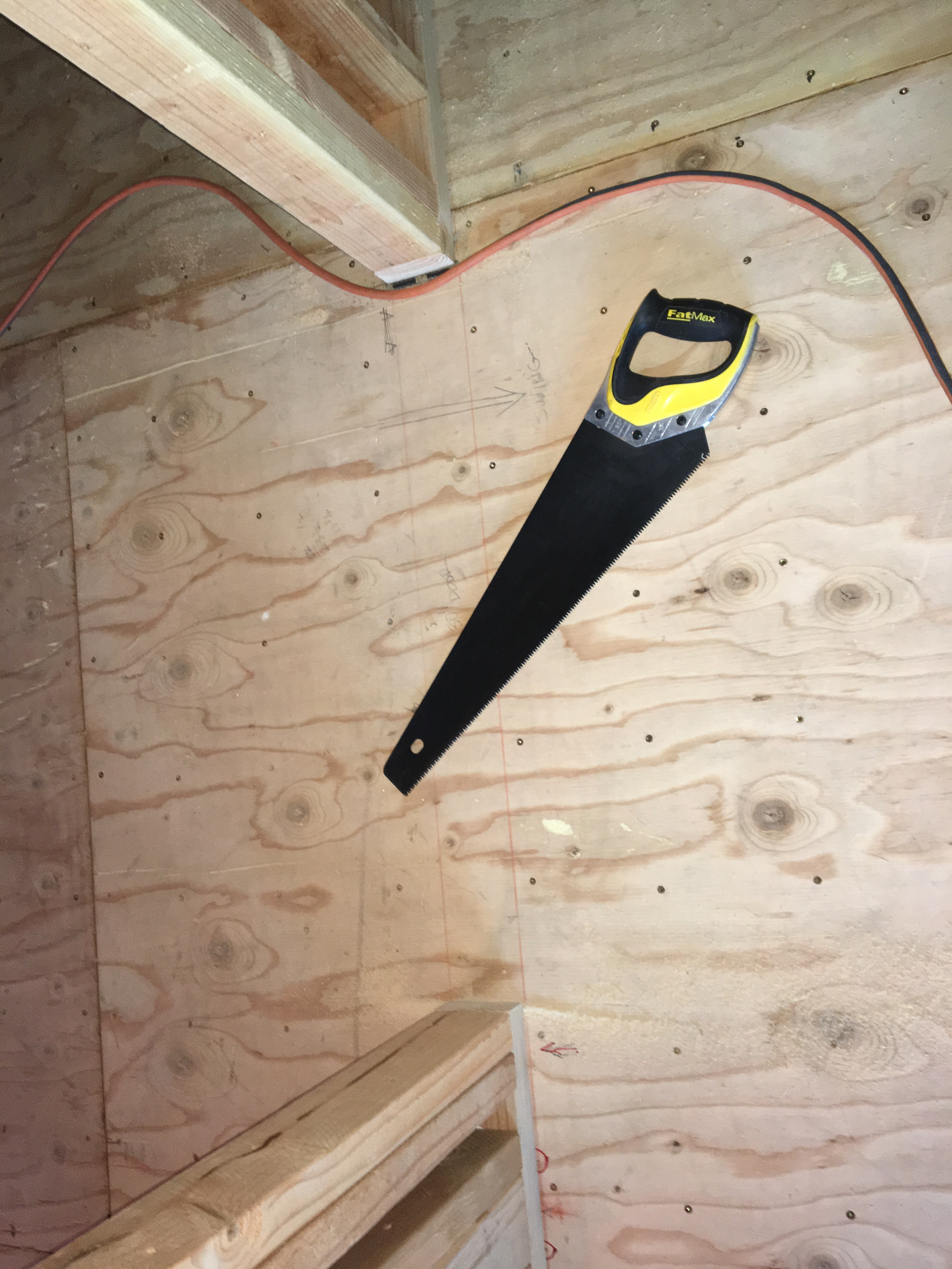
Sole plate is now cut for the door opening.

Now that the interior framing is in place, it’s time to proceed to the next step: rough plumbing, electrical, and data lines.

A New Garage Door

I had been thinking that installing the garage door would be one of the last things on my list because I didn’t want to have to put drywall in and around all of the various hangers and fixtures that are a necessary part of the installation. However, putting in the door now would help finish off the exterior, and let’s face it, the old garage door was looking especially sad in the context of all of the other new work. Another reason was that the door was a swing-out slab, and when it was open, the bottom stuck out and was a head-strike hazard because of the way I changed my sidewalk. So, it was really time for it to go.

One last look at the old garage door. It lasted a long time, but it needed a reboot.

One of the main reasons that I wanted to replace the old garage door is that it sticks out when opened and you can hit your head if you’re not careful. I discovered this the hard way…

See?

I discussed this possibility with one of my co-workers (who also happens to help me when I need an extra pair of hands), and he told me that garage door installation was pretty straightforward. He had done several, but also cautioned that you needed two people to put the sections in place. Plus, he said he would help me out when the time came. I was sold.

Putting in a new garage door and opener is well within the capability of the DIY’er who has a reasonable amount of experience. Having said that, you really need to respect the loads and forces that will be involved. That means that you need to do your homework and read the installation instructions and watch a few YouTube videos on how to do the installation. It’s also important to understand how the entire contraption works, which parts do what, and why you are assembling them in a certain way and sequence.

Back to the job at hand. I got online and found a few places that deliver made-to-order garage door “kits”. It turns out that you can get these same garage doors from dealers and installers as well as big box stores (Home Depot, Lowe’s, Costco). Two of the popular manufactures are Clopay and Amarr. I chose Amarr because I liked the available styles and options. There was a 3-4 week lead time for delivery, so I placed the order and began scheming and plotting the installation. This included downloading and careful study of the installation instructions.

Read the instructions! Note that I’ve highlighted the specific sections that were applicable to my installation.

The day came for delivery and I took the entire day off because my plan was to do as much preparation work as I could before my helper came the next day. I started by cleaning up the garage (seems as that’s a constant task), and then installing some additional framing around the door opening (or “jamb”). This framing is important because you’ll be attaching the tracks and the torsion spring to it, so it needs to be very solid and securely fastened to the rest of the framing. I also took the time to furr out some of the door header and pre-install sheetrock so I wouldn’t have work around the garage door parts later.

First thing is to clean up the garage so I’ll have an area to work in.

Here is the new framing for the jamb. This framing needs to be sturdy because it will be taking a lot of force from the door tracks and springs.

This is the torsion pad. It needs to be securely fastened to the header. I used 4-1/2″ Simpson structural wood screws (SDS). They are easier than lag bolts because to install because you don’t have to pre-drill a pilot hole. Plus they’re stronger.

I put the sheetrock up behind where the torsion rod and spring would go to make finishing the garage easier later.

My delivery truck. This truck had about 8 other doors kits for delivery to other homes. I guess I was in good company today.

The garage door parts all delivered. The door sections are on the right and there is a big cardboard box on the lower left stuffed full of hardware.

Next was the assembly of the hardware onto the individual door panels. Each panel is 16′ long by 21″ high. They’re pretty unwieldy, but one can move them around if you get in the middle and move slowly. These were much easier to handle than 20′ 2×12’s that I had to tug about when I was fixing my bedroom joists. The time I spent in reviewing the instructions paid off here because I was able to quickly recognize which part was what and where it went. That’s important when you’re staring at a box of about 300 parts and you need to sort them out.

It turns out that installation instructions are sometimes only so good. In this case, I had to install “struts” which are basically longitudinal reinforcements on each door panel. It was not clear from the instructions how to line up all of the holes, and, indeed, it seemed that several holes were not lining up at all. After about 30 minutes of head scratching and going to the computer to get a magnified view of the plans (thanks to PDF), I was able to figure out how it all went together and that I simply needed to drill some holes where they “should” have been. Bottom line is that sometimes you need to be a little smarter than the instructions.

Door panels with hardware installed. They are stacked in in order so we can just flip them up and put them on top of one another.

The next day, my helper came and we pulled down the old door, reconfigured the side jambs for the new door, and then commenced installation. We got the panels in place, and then I spent the entire next day putting up the tracks, installing the torsion spring and lifting mechanism, and installing the opener.

Here is my colleague from work who is a very reliable helper. I couldn’t have done this project without him.

Track hanger installed. I needed to do some adjustments later when I pulled up the door.

This is the torsion spring. The winder is in the middle. It’s a really nice setup because you just chuck in a 3/8″ socket to your electric drill and go to town. Winding the springs was essentially effortless.

I won’t go through all of the details because there are many videos and how-to’s which show the process much better than I was able to document. However, I do have a few suggestions:

Take advantage of the fact that the hardware is designed to be adjustable. You will likely have to accommodate some degree of error in your door opening and floor in order to get the door plumb and square. The door can also operate with a certain amount of tolerance, so things don’t have to be super exact. But you want to do a good job, yes? So get things as close as you can. I had to tweak things several times after the installation was complete as I noticed that this or that didn’t align just right. Every time I made an adjustment, the door operated that much smoother.

Use SDS screws in place of lag bolts if that hardware is not provided with the door. Examples include attachment of the spring pad and the rear track support hangers. SDS screws don’t require pre-drilling and are actually stronger.

Cut the top of the diagonal back hanger support at an angle so it fits flush against the drywall.

Cut the end of your track hanger brace so it lies flat on the bottom of the ceiling.

Track hanger brace installed. See how the top of the angle lies flat against the sheetrock? Believe me, you won’t be able to get the holes to line up if you don’t cut off that little piece.

The door was misaligned a bit when I first operated it. I didn’t notice at first and ended up damaging the door seal on the right side. NBD, that’s something that’s easy to replace.

Take the time to do a neat and professional installation. This includes running the wires for the opener neatly, and hidden if you can. I mounted my opener button to an electrical box and ran all the wires where the would be hidden by sheetrock (eventually). These details caused me to run our of bell wire and bell wire staples (the opener didn’t come with enough material), but the effort was worth it. Don’t forget the safety stickers!

Door operating switch. I mounted this to an electrical box so the installation is clean after the sheetrock is in place.

When I do a job, I want others to think that a professional did it. Installing the safety stickers is something that the pros do (or should do).

I always sign my work. It’s a nice personal touch.

My opener is really slick (Liftmaster 8500). If you have a garage door with a torsion spring, this is the opener you want. Every door on the delivery truck had a corresponding Liftmaster 8500, so that’s what the pros are using.

The opener mechanism is very compact and operates the door through the torsion bar. This design eliminates the bulky motor and bar in the middle of the garage ceiling. If you get a new garage door installed by a pro. it will likely come with one of these.

The opener comes with an electric door lock. The bolt sticks through the track and prevents the roller from moving past it.

Pay attention to how you install the light beam transmitter and receiver. Make sure you place the receiver on the opposite side of where the sun shines. If you install the receiver on the side which receives direct sunlight, as mine does in the late afternoon, then the sun will blind the receiver and the door won’t work. The receiver is the device that has what looks like a big glass eyeball. I thought it was the other way around until I installed it incorrectly and realized my mistake.

This is the sender for the “light” beam that is a part of the door’s safety mechanism. It emits infrared light so you don’t see it. The amber LED shows that it’s on. This is located on the side of the door that gets sun in the late afternoon.

This is the light beam receiver. It has a green LED and if it is lit, that means that the light beam circuit is working properly and that the door will operate (or if it doesn’t, then that’s not the problem). I found that the light beam is usually the cause of a door operating problem.

Here is a video that summarizes how I did the installation:

A DIY Take On Garage Door Installation

The house exterior is almost done! The inside is another story……

Lookin’ good! I’m getting lots of compliments from my neighbors.

California Sleepin’ — Finishing up the Porch Roof and Getting Ready For Roofing And Stucco

Alas, even though I had been working hard on getting the framing and roofing done, I still had to build the roof system over the porch. This was going to be some more fancy carpentry than what I did in the past because I had to put together a new roof structure and stitch it up to the existing roof structure. I did much of the work during the design phase, so my plans were pretty detailed. But, before I could proceed, I needed to build a proper structure to support the roof and the associated framing.

The first thing that I had to do was to replace the old beam and column which held up the balcony with a new structure. The old one was falling apart, and most of the construction was more of this slipshod crap from the original builder. I try to replace as much of this crappy work as possible without tearing down the whole house! This, however, was a no-brainer, and not very difficult when compared to building the main addition. I started with a bare foundation, then drilled holes and put in new anchor bolts secured with epoxy. I learned the proper way to do it when I did the seismic retrofit in the garage. Next was some simple vertical framing for the column proper. The main thing I had to consider was how to protect the top of the column from weather. I put in two sheets of building paper with some flashing on top, and made sure to have about 3-4 inches of overhang so that the stucco folks could tie it in when they did the lath.

New hold down bolts properly held in with epoxy.

New hold down bolts properly held in with epoxy.

Close up of the porch column with building paper (2 layers) and flashing installed. The stucco people will like me for this.

Close up of the porch column with building paper (2 layers) and flashing installed. The stucco people will like me for this.

I also had to tear into the wall of the house to get to the old beam and remove it. Good thing I did because the wall support for the old beam was totally inadequate. I replaced it with a proper 4×4 and fastened everything together with SDS wood screws. That baby ain’t coming apart!

New in-wall support column for the porch beam. The other one was a crappy little 2x4 that was all bent. Note the SDS screws which secure the beam the the wall structure.

New in-wall support column for the porch beam. The other one was a crappy little 2×4 that was all bent. Note the SDS screws which secure the beam the the wall structure. “SDS” stands for “Strong Drive Screw”, which is a proprietary name for these screws made by Simpson Strong Tie.

New column and beam for the porch roof. The old assembly was falling apart and the support column in the wall behind was just lousy, sloppy construction.

New column and beam for the porch roof. The old assembly was falling apart and the support column in the wall behind was just lousy, sloppy construction.

The next thing to do was to lay out the roof structure. Roof structures are made with either trusses, which I had to use over the master bedroom, or simple framing lumber put together one piece at a time. This is called “stick” framing when you’re doing it for a roof. Before I get too far into how I did this, I think it’s helpful to be familiar with some of the terminology. As with walls, each structural member has a name. The board going across the top is called the “ridge”. This is supported at each end by walls called “gables”, if they are straight up and down, or “hips” if the roof slopes at the ends, as well as the sides. The framing of the roof from the ridge board to the top of the walls is called a “rafter”, and the lumber going from the top of each wall across is called a “joist rafter”. For more complex roofs, you have “hip rafters” which are at the edges of hip roofs, “valley rafters” where a one roof line intersects another forming, well, a valley, and “jack rafters” which are the short rafters going between the hip rafter and the top of the wall, or the valley rafter and the ridge. Here is a picture to help sort things out.

Basic diagram for roof framing. There are all kinds of references and resources on the Internet.

Basic diagram for roof framing. There are all kinds of references and resources on the Internet.

My porch roof was a little different (naturally). The roof is only “half roof” that starts halfway up the second story wall and slopes down over the porch, so the ridge board becomes a “ledger” board. And, instead of intersecting the main roof with a valley, I have to put down lumber on top of the main roof. I came up with this idea by myself during the design phase, but little did know that my situation was not unique. In fact, I found that the proper terminology for this piece of lumber is called a “sleeper”, and because this happens a lot in California (God only knows why), it’s called a “California sleeper” — hence the title of this post.

This shows the structure detail of the porch roof.

This shows the structure detail of the porch roof.

Now that I actually had to start cutting lumber, I was faced with the conundrum of figuring all of those pesky things like lengths, miter angles, and bevel angles. I also knew from past experience that little errors are magnified when you start cutting angles. I did some research on the Internet and I found a REALLY GOOD roof framing website by a master carpenter named Sim Ayers who had a blog entry on EXACTLY what I was trying to accomplish. So I read with enthusiasm and discovered that calculating these lengths and angles directly from trigonometry was pretty tedious. While there are some handy-dandy roof calculators out there, I decided that I already have a “calculator” in with my 3D modeling program. Since I wanted to be as accurate as possible, I used some direct measurements, which are always good when you’re working with existing structures, and then fed them into a simple 3D model and took off the necessary lengths and angles (bevels and miters) from there.

3D model of the porch roof where it joins the main roof. I only took 3 orthogonal measurements (as shown) and constructed the rest of the model from there using the known dimensions of the lumber and the rafter spacing (16

3D model of the porch roof where it joins the main roof. I only took 3 orthogonal measurements (as shown) and constructed the rest of the model from there using the known dimensions of the lumber and the rafter spacing (16″ o.c.).

Close-up of the

Close-up of the “sleeper” rafter and how I measured the cut angles. The 3D modeling program gives me the exact angles.

I know this isn’t a really useful “how to” unless you have a 3D modeling program, which I highly recommend anyway, but really, if this is something you’d like to know more about, then visit Sim’s website (link above). Here is the link for his blog post on Off Angle California Framing.

Picture of a

Picture of a “pro” roofing job (by Sim Ayers) using a California sleeper.

My DIY version. That was some pretty fancy carpentry!

My DIY version. That was some pretty fancy carpentry!

Once I had the rafters and trim in place, I needed to get the roof on. I decided to use shiplap on the entire roof because the underside would be exposed and I wanted a nice look.

Underside of the porch roof matches the shiplap of the eaves.

Underside of the porch roof matches the shiplap of the eaves.

Front wall extends up to the last common rafter. Note the small space between the main roof, the adjacent wall, and the porch roof. This will be totally closed off when complete. Maybe I'll cut a small hole in the bedroom wall and use this as a

Front wall extends up to the last common rafter. Note the small space between the main roof, the adjacent wall, and the porch roof. This will be totally closed off when complete. Maybe I’ll cut a small hole in the bedroom wall and use this as a “secret compartment”.

I always sign my work. This area is going to be covered with plywood and stucco. I wanted people 2000 years from now to uncover my hieroglyphics during an archeological dig and argue for decades about what this find meant.

I always sign my work. This area is going to be covered with plywood and stucco. I wanted people 2000 years from now to uncover my hieroglyphics during an archeological dig and argue for decades about what this find meant.

Now, before I got the windows installed, I wanted to load the bedroom with any additional drywall and lumber that I might need because I sure didn’t want to haul it up the stairs! Fortunately, I could rent something called a “material lift” which makes it possible.

Drywall and lumber ready for loading up into the master bedroom. I wanted to get this loaded before I had the windows put in,

Drywall and lumber ready for loading up into the master bedroom. I wanted to get this loaded before I had the windows put in,

I rented a material lift to get all of the plywood and drywall up to the second floor.

I rented a material lift to get all of the plywood and drywall up to the second floor.

Unfortunately, I had some “learning” to do when it came time to actually use it as the following video shows.

Despite my failings, I was able to get the materials loaded and the windows installed.

Drywall and interior lumber loaded into the master bedroom. That was a LOT of WORK!

Drywall and interior lumber loaded into the master bedroom. That was a LOT of WORK!

All buttoned up and ready for the lath folks.,

All buttoned up and ready for the lath folks.,

Upon This Rock I Will Build My House

With demolition largely complete, it’s time to start building! Well, not quite so fast. Demolition being “largely complete” simply means that I’ve done as much as I could without actually opening up the house. This is an important distinction because once you open up the house, you have to work like hell to build it back up so that the varmints stay outside. Especially the ones who are walking by and see your expensive tools and want to take them.

My new pneumatic nail gun. The new tool for this project. I know, a REAL framing carpenter only uses a hammer, but nobody does that anymore these days.

My new pneumatic nail gun. The new tool for this project. I know, a REAL framing carpenter only uses a hammer, but nobody does that anymore these days.

At any rate, I was ready to build the portion of the garage that was directly under the new bedroom addition. Originally, I planned to keep the existing structure and simply reinforce it and put plywood panels on the outside to make new shear walls, and build a new deck overhead. But, alas, when I removed the drywall, I found that the framing around the garage door, commonly referred to as a “portal”, was not even close to the required specifications. So, I had to take down all the walls and start from scratch, building up from the foundation. It was probably just as well because the existing framing, although adequate, was lacking somewhat in craftsmanship and accuracy. Best to get a fresh start. But I had one “big” problem.

One of the hallmarks of this project is that I’m doing EVERYTHING myself. So, I typically have to give some thought about how I will handle materials without help. In most cases, I can rig up a “third hand” or find a way to wrestle this or that into place, and sometimes have to come up with a mechanical solution (e.g., ropes, pulleys, chains). In this particular case, I had to figure out how to lift a REALLY BIG BEAM into place. I’m talking 3-1/2 inches thick by 16 inches tall by 20 feet long. While contemplating this at work, I mentioned my conundrum to one of my co-workers, who happened to have some extensive remodeling experience himself. He said, “Let’s just get some folks together and muscle this thing into place. It won’t take but a few minutes, if everything goes right, but let’s plan on a few hours because I’m a believer in Mr. Murphy.” He was referring to Murphy’s Law: If anything can go wrong, it probably will. So, with some cajoling, I was able to enlist the help of another co-worker and my oldest son, and arranged for a Friday morning beam raising ceremony. I also got my plumber scheduled so he could re-do the water service entering the house. This was important because I had run the water line through the front and needed to have the line disconnected to get the shear wall in place.

Now the pressure was on! I took 3 days off from work, figuring that I could get the demolition done and the framing up to accept the beam during the first two days, and be all ready by the appointed time on Friday morning.

The front of the house sure looks different with the balcony removed.

The front of the house sure looks different with the balcony removed.

Day one, Wednesday: Let the demolition derby begin! The first thing to do was to remove the old balcony floor. It turned out that the subfloor was attached with screw nails and it was a real bitch to lever off the plywood, and of course, it took much longer than anticipated. I then had to disassemble the joists underneath. I found out that I could knock them sideways and they came right down. Then, I had to remove the stucco from the walls.  This is one dirty, tedious job that requires a lot of muscle work. Never mind that I had to take my 7″ grinder and precariously balance myself on top of a stepladder while getting all that dust in may face. Fortunately, I was smart enough to wear full goggles and a dust mask. Still, the goggles fog up and you end up getting covered with that crappy dust and end up looking like the Pillsbury Dough Boy. Needless to say, this took longer than anticipated (do you see a pattern developing?) and I had to stop before I could finish. Plus I was dead tired. I figured I could make up the time tomorrow. But first, I had to clean up and then install a big piece of black visqueen across the garage opening. I wanted to discourage random thievery and I figured that hiding everything would at least keep my valuable tools out of sight.

The stone that the builder rejected has become the chief stumbling block.

The stone that the builder rejected has become the chief stumbling block.

Day two, Thursday: Despite being exhausted from the day before, I had trouble sleeping because I was cramping up. That’s what happens when you hit your body hard with a bunch of exercise (as I know from my triathlete days). But woke up early because I knew I had to catch up. Went to Home Depot to get some pressure treated lumber for new sill plates because the existing ones looked like hell and I figured now would be the time to replace them. More unanticipated work. I still had one wall to knock down and some additional stucco to remove, but I couldn’t start because my lumber delivery came. It was one big load all strapped together, so the driver just slid it off the truck and onto the driveway. So, I had to move it all around in order to clear the driveway, but it was just as well because I re-stacked it in the order I needed to use it, which would hopefully save some time later. And it was getting later. By the time I had finished the remaining demo, and cleaned up, it was noon. Putting in the new sill plates took some time, but I figured that the wall framing would be pretty easy. I cut all of the lumber to the sizes I needed, but was only able to get one of the walls together and up before it got dark. And I was totally out of gas. Time to get some rest for the big day tomorrow! But first, I had to clean up and put that damned plastic back up.

Day three, Friday: I couldn’t sleep last night either because I knew I had to get that last wall up and I had folks coming at 7:30. Fortunately, I was able to get the wall framing assembled on the ground, and my son showed up to help me wrestle it in place. I was just finishing up when the rest of the crew arrived, and it was time to raise the beam! After a few minutes of strategizing, we all grabbed it and muscled it up there. I tacked it in place, but then Mr. Murphy showed his ugly head. I realized to my horror that I made the end walls 3″ too short! How could that be?? Well, like a dumb-ass I subtracted the double top plate, which I shouldn’t have done. Now we had to take out some nails, which was pretty damned difficult, and raise the beam enough to slip in a couple of 2×4’s underneath to get everything level. Unfortunately, we had to do this one side at a time, which meant that there were some small gaps at the ends because lifting up the beam on one end, even by 3″ threw it slightly out of level. In the end, I was only about 1/2″ off, but still you could see some gaps. Ultimately, gravity will settle things somewhat, but it was a little disappointing. Nevertheless, my plumber came and did his typically excellent installation, so I was able to get up most of the shear panels and ended the day with something that looked like a proper structure. After clean up and putting the plastic up (again) I could go in with a sense of satisfaction.

Day four, Saturday: Once again, I was working by myself. I got the rest of the shear panels up and then had to install some additional framing around the garage door opening so that I could re-install the garage door. I didn’t want to keep putting plastic sheeting up, plus I sure didn’t want to leave the house wide open when I went back to work on Monday. This took longer than expected because I decided to put some additional framing in to more easily locate the seismic hold-downs. I then had to attach a 20′ 2×12 to an existing beam that would support the joists of the bedroom addition floor. When I did the plans, I figured that what was existing (a built up beam of 3-2x12s) was good enough, but the plans examiner INSISTED that I put in another 2×12 and secure the whole assembly with a bunch of 1/2″ carriage bolts. At the time, I though it was overkill, but as I tried to marry up the new 2×12 to the existing structure, lo and behold, the existing beam was sagging. I mean by a very noticeable amount, like over an inch! So, I guess the plans examiner was right all along, and I now thank him for his advice. I wasted an hour trying to jack the existing beam up with what I had, but the more I thought about it, I figured the only way to straighten the whole thing out would be to replace it — a non-starter. So I did what a lot of remodelers end up doing, which is living with what you have and adapting. There will be a discontinuity when the new floor meets the old floor, especially in the center, but I’ll deal with that later. I also had to waste another hour or so cutting out the bottom of the aluminum framing around the sliding glass door.  The new lumber was hitting it and wouldn’t go flush to the existing built-up beam. As usual, time flew and by the end of the day, I only ended up getting the new 2×12 tacked up and in place. Still had to install all of those bolts.

New joist all bolted into place. See the gap between the bottom of the new joist and the bottom of the existing beam?

New joist all bolted into place. See the gap between the bottom of the new joist and the bottom of the existing beam?

Day five, Sunday: I really wanted this to be a day of rest, but I spent several hours after church re-installing the garage door. It was a little fussy, but I got it in and working. This was good because now the garage had some physical security and I felt OK locking it up and leaving it. All the tools were out of sight, and it would take some doing to climb up and around to get into the place. So much for the “big week”. At least I got stuff closed in a bit, which removed some of the pressure to meet deadlines. After all, this is supposed to be enjoyable, eh?

The garage door re-installed and my tools safe from random thievery.

The garage door re-installed and my tools safe from random thievery.

Here is a video of the whole thing:

Now my attention turned to installing hardware. Besides the bolts for the new 2×12, and joist hangers and hold-downs for the new joists, I had to figure out where to drill holes in the foundation to install threaded rods glued in with a special epoxy to meet new code requirements for seismic loads. I had a pretty good idea where most of them should go, but there was a tricky spot in the corners next to the garage door opening. Additionally, the special epoxy installation needed a “special” inspection, meaning that an inspector certified in this sort of thing had to inspect every hole for proper depth and cleanliness before you put the epoxy goop in. So I figured I would ask the inspector about the bolt location AHEAD OF TIME. Note my predilection for avoiding future trouble caused by me.

Proposed hole locations. I really didn't know how to do this correctly. At least I realized this ahead of time.

Proposed hole locations. I really didn’t know how to do this correctly. At least I realized this ahead of time.

I looked up special inspectors on Angie’s List, and while Angie’s List is usually pretty good, here I found nothing. So I searched on the Internet and found a guy whom I contacted. He was very cooperative, and since I did the design, I knew the requirements so I was able to give the impression that I knew what I was doing. I sent him a picture of the proposed hole locations, and he contacted a colleague who happened to be a registered Professional Engineer (PE) to get his advice. After some back-and-forth, I contacted the PE, whose name is Chris Pinnow (see link to his website) and arranged for a meeting. As the appointed time came closer, he was running late and suggested that he would come the following day (Saturday) AND he would bring a hammer drill and bit and offered to help drill the holes and knock off the entire job! It was pretty easy to say yes.

"My" engineer- Chris Pinnow. Really glad to have met this guy.

“My” engineer- Chris Pinnow. Really glad to have met this guy.

Sure enough, he shows up and we get to work, and in 4 hours I have all the holes I need, properly inspected with threaded rods properly secured with that special epoxy. Turns out that I had some misconceptions about what the hold downs were supposed to accomplish, and I’m really glad that Chris came and checked things out, because he made some crucial corrections to the installation. Here is the lesson: The days of framing a house with a stack of 2x4s, circular saw, and a big box of nails, are over. Today’s construction techniques are pretty sophisticated and if you’re doing something on the order of a remodeling job that involves structures, you’d better find a PE that can help you look at a few things should they come up. Their prices are usually very reasonable for professional services, and their advice is well worth it because you won’t have to do things over.

Final location of the holes, per my engineer.

Final location of the holes, per my engineer.

New hold down bolts all glued in place.

New hold down bolts all glued in place.

With that out of the way, it was time to build the deck over the garage, which serves as the structure for the floor of the bedroom addition. Ordinarily, this would be a relatively straightforward task, and if you were building totally new construction, it’s a day’s job, even if you’re solo. But with remodeling, usually nothing is so straightforward. That’s because the old stuff has most likely moved around a little bit due to settling. Plus, sometimes the carpenters who build the house may not be so fussy about accuracy, especially if they’re building a tract house and time is of the essence. So, things are not necessarily plumb or square, and you have to accommodate this when you meet up the new with the old. In my case, the built-up beam that supports the existing bedroom gable wall was not only sagging, as mentioned above, but was also bowed out and canted forward. That meant that I had to not only cut each joist to a different length to accommodate the bow, but also cut each at an angle so they would meet up correctly with the canted face. But, hey, it gives me a chance to exercise my craftsmanship skills.

Old meets new. Note the sag in the existing beam as compared to the new joist. Also note the location of the chalk line.

Old meets new. Note the sag in the existing beam as compared to the new joist. Also note the location of the chalk line.

Notice the difference in the position of the chalk line. This shows the bow in the existing beam.

Notice the difference in the position of the chalk line. This shows the bow in the existing beam.

My worksheet to keep track of what joist goes where.

My worksheet to keep track of what joist goes where.

I had to cut each joist at an angle to take into account the cant of the existing beam.

I had to cut each joist at an angle to take into account the cant of the existing beam.

All joists are up. Still have to add the rim joists.

All joists are up. Still have to add the rim joists.

Deck framing complete with rim joists installed.

Deck framing complete with rim joists installed.

Blocking detail. These are short blocks of wood that fit in between the joists. This not only gives the structure a lot of additional strength, but also squares up the joists nicely. Note the tight fit in the corners. Really looks nice!

Blocking detail. These are short blocks of wood that fit in between the joists. This not only gives the structure a lot of additional strength, but also squares up the joists nicely. Note the tight fit in the corners. Really looks nice!

Now with the framing in place, it was a simple matter to install the plywood on the frame to make a nice solid deck for the bedroom floor. I was a little concerned about fitting together the tongue-and-groove plywood together by myself, but I came up with a nifty way to do it. All you have to do is to get one corner started and then temporarily secure it with a deck screw to the joist below. Then you can coax the whole assembly together using the deck screw as a pivot. Here is a picture:

How to mate tongue and groove plywood by yourself.

How to mate tongue and groove plywood by yourself.

With the deck in place, it was time for an inspection. This was important because if I don’t have an inspection every 6 months, the city assumes that my project has been abandoned and they cancel my building permit. Because I can only work so fast, and I didn’t have a lot of inspectable items while I was working on the outside, AND I used up my one-time extension, this was a big deal. The inspector came and had some good words of advice, particularly when he pointed out that I had installed the washers on the hold-downs upside-down. How embarrassing!!

New hold down ready for inspection. Note the position of the U-shaped washer under the nut. I had a little surprise coming.

New hold down ready for inspection. Note the position of the U-shaped washer under the nut. I had a little surprise coming.

Hold down properly installed (!)

Hold down properly installed (!)

Nevertheless,  I got a couple of inspections signed off, so I punched my card for 6 more months. This whetted my appetite for the BIG buildout of the master bedroom, which is next!

New deck installed.

New deck installed.

The proud builder atop his masterpiece.

The proud builder atop his masterpiece.

And The Walls Come Tumblin’ Down — A Short Discourse In The Art Of Demolition

Demolition. The word itself evokes images of fire and brimstone, mass destruction and the wailing masses. If you watch some of the home improvement shows on TV, you’ll typically see the homeowners doing some wailing of their own, albeit of a different ilk. Take that sledgehammer and just beat the living daylights out of everything you see and you’ll be a REAL remodeler! Well, I am here to tell you that what makes good reality TV makes a horrible approach to a demolition project. Swinging a crowbar and acting like a drunken oaf is a waste of time, effort, and money, and a more thoughtful approach can save you all three.

Enter the “art” of demolition. As with most things in life, a good demolition project starts with a good plan. It turns out that there is a lot to consider: How much and of what type of demolition byproduct will be produced? How do I get rid of it? How big of a dumpster do I need? Do I need a permit? (Typically you need an encroachment permit if you use  dumpster that goes on the side of the road.) Am I dealing with any hazardous material (e.g., lead or asbestos)? What are the areas to be demolished and how do you account for the new structure(s)? How does the demolition sequence affect the building sequence or vice versa? Am I removing any load-bearing structure that will need temporary bracing? What tools are best and do I have to obtain any? And this is not an exhaustive list. Is demolition a DIY proposition? Well, I guess that depends. If it’s a small project like remodeling a bathroom, then it definitely can be DIY. If you’re busting out a load bearing wall and building an addition, then it can be DIY, but you’d better have some previous experience so you have a pretty good idea of what you’re doing. If you’re going to demolish an entire house, well, that’s probably not DIY.

Equal in importance, or perhaps more, is safety. I cannot emphasize this enough. Perhaps I’m a bit anal when it comes to safety, and my background in industrial and military environments has given me a certain viewpoint about it. There are two ways to approach safety, protection and prevention, and it’s important that you incorporate both approaches because they work hand-in-hand.

First, protection. Protection is all about minimizing the dangerous effects of a hazardous environment. To be more specific, you need to protect yourself physically from the potential dangers of your work. Of all the protective gear that you can get, eye protection is probably the most important. Unless you’re reading your plans or answering your smartphone, I can think of very few construction activities that do not involve the potential for stuff flying around and getting in your eyes. Next on the list is probably gloves, followed by hearing protection and foot protection. For demolition in particular, breathing protection becomes a big deal, as does a hard hat. If you’re going to deal with hazardous materials, like lead or asbestos abatement, then add protective coveralls to your outfit. This is by no means an exhaustive list, so the best approach is to think carefully about safety before you start the job and make sure you’re properly outfitted.

Prevention means stopping a hazardous situation from existing or developing, and this requires constant thought about what you’re about to do next. If you’re going to be working on a ladder, then make sure it’s properly situated and don’t exceed the recommended standing height (i.e., don’t stand on the top step). Keep clutter to a minimum so you don’t trip and fall. That’s quite important during a demolition project, so the orderly and periodic removal of debris should be part of your plan. Make sure your cords from your electrical tools are out of the way so you don’t cut into them. If you’re going to work on the second story or roof, then consider renting scaffolding. Safety when working with power tools is all about prevention, and one must be constantly aware of where the dangerous parts of the tool are so as not to injure yourself or others. To sum up, I would say that prevention is more of an attitude and state of mind. You have to make it a priority and, really, always be thinking about it.

Wow. All that talk about safety got me fired up! Was it good for you too?

Now onto the real deal. Removal of a stucco wall that formed a balcony (i.e., a pony wall) outside my master bedroom was first on the list. While it may be tempting just to take a sledgehammer and wail away, there really was a much easier way to approach it. The first thing I wanted to do was to prevent the debris from falling on my new sidewalk, gate, and railing, so knocking down from the inside-out was a non-starter. What I decided to do was to disassemble it in basically the reverse order of the building, and then take it apart into smaller pieces that could be tossed onto the driveway. This meant taking off the top trim, which I would use later to weight down some visqueen on the driveway, giving me a large target to toss the debris onto, while helping to protect the driveway.

DSC_0039

House with balcony, before demo.

Balcony trim and top plates on a sheet of visqueen. This helps prevent damage to the driveway when I toss stucco slabs over the side.

I then pulled off the stucco from the inside of the wall to expose the framing. There is a technique for stucco removal, which I learned from my favorite stucco guy on YouTube, Kirk and Jason Giodarno. Here is a video:

There are two key elements to this technique: (1) cut the stucco into small enough sections so that you can move them around  — stucco is heavy!, (2) cut THROUGH the lath (wire mesh) that holds the stucco together. If you bash stucco with a sledge, you’ll get a bunch of stucco turds all connected by the underlying lath. Totally impossible to work with!

A 7″ grinder with a wet-dry masonry wheel. Essential for demolishing stucco.

Stucco all cut into sections for ease of removal.

First slice of stucco removed.


Inner balcony stucco removed.

Once the stucco was off the inside, I pulled up the lumber that connected the tops of the studs (top plates). I then cut the stucco from the inside, which is easier because the lath is closer to the inside, so you don’t really have to cut all the way through. Once I made another cut spaced by two studs, it was an easy matter to pull the section of stucco and studs inward. The weight of the assembly and the leverage I was able to provide caused the lath at the bottom to fail, and the whole thing just plopped down in front of me. Now I could knock off the studs and cut through the lath to make the stucco slabs small enough to handle.

Balcony debris. Because of the sequence, I had to walk over this stuff until I opened up a hole in the outer stucco so I could toss this stuff onto the driveway.

First section of outer stucco is removed. This gives me a “window” to toss the debris onto the driveway without having to lift it up and over.

The balcony wall safely in the protection of the dumpster.

The front of the house sure looks different with the balcony removed.


With the outside done (to a point), I started the demolition of the master bedroom which is really the main part of the remodel. Because I am a diligent homeowner, knowing that I had an older home, I tested the popcorn ceiling for asbestos. Actually, I was also motivated by the $25,000 fine that might be levied against me for improper asbestos disposal by the EPA. Sure enough, I had asbestos, so I needed to take some precautions. Now, before I get into the details about this being a DIY job, I want to make a few disclaimers.

  1. I have formal training and experience in asbestos removal and remediation from my Navy days. The older engine rooms used asbestos to keep the steam pipes insulated, and because I was the officer in charge of maintaining an engine room built in the 1950’s, I needed to know my shit.
  2. I have formal training and years of experience in handling and disposing of hazardous materials (HAZMAT) and nuclear waste.

Having gotten that off my chest, allow me to say that proper and safe removal of an asbestos popcorn ceiling isn’t particularly challenging from a technical standpoint. You just have to use some common sense and understand exactly what the hazards are so that you can protect yourself, and others, against them. The main thing to remember about asbestos is that it is the airborne particles that cause all the problems. And they are big problems. Basically, any asbestos particles that you inhale will stay with you for the rest of your life. They become embedded in your lungs and you can’t get rid of them, and their sharp edges provide a constant source of irritation that can eventually develop into mesothelioma and lung cancer. So, airborne particles are the enemy. Let’s go back to my original safety mantras of protection and prevention.

To protect yourself against asbestos, you need to be fully covered in a HAZMAT coverall with a hood, wear disposable gloves, have full goggle eye protection, and a respirator with filters.

All suited up for asbestos! I needed to have one hand ungloved to take the picture. Otherwise, I'm ready to go!

All suited up for asbestos! I needed to have one hand ungloved to take the picture. Otherwise, I’m ready to go!

The good news is that you can buy an asbestos removal “kit” online (PK Safety) for around $30. Since the popcorn material is usually low in asbestos (2% – 3%), you do not need a fully sealed, forced ventilation suit and mask (yes, I’m familiar with those as well). So, you’re getting off easy.

To prevent, or at least minimize contamination, there are two things that should be done. First, seal off the area, meaning tape some plastic over the door(s) to other rooms, and put a plastic dropcloth on the floor. This dropcloth simplifies disposal because you just wrap it up and double bag it, popcorn and all. Second, use some water from a garden sprayer to wet the popcorn. This not only helps keep the asbestos from getting airborne, but also makes scraping the damn stuff off pretty easy.

One last thing before I suited up was to make sure that I had EVERYTHING I would need at hand. Once you suit up and start, you don’t want have to stop in the middle because it’s usually difficult to get out of the suit, and even harder to put it back on (if you don’t destroy it when you take it off). Go to the bathroom, even if you don’t feel like it.

You’re welcome.

Tools for asbestos removal. A garden sprayer and scrapers. Pretty basic.

Tools for asbestos removal. A garden sprayer and scrapers. Pretty basic.

Trash can all ready to load the asbestos popcorn. Getting this ready before I suited up saved me some time and aggravation.

Trash can all ready to load the asbestos popcorn. Getting this ready before I suited up saved me some time and aggravation.

So, I mentioned that removing this stuff was not technically difficult. Just spray some water onto the ceiling to cover an area that you can reach with your stepladder, and take a wide-bladed scraper and ease the stuff off in big strokes. Then clamber down the ladder, being careful not to slip on the goop that you just plopped on the floor, move the ladder, and start again. Did I mention that the coveralls get hot, and that your goggles fog up and get poopy popcorn on them that you have to wipe off and you still can’t see? You get the picture. Technically difficult, no, but tedious and uncomfortable, yes. Much like other things in life, eh?

First section of asbestos popcorn removed. Note that the ceiling is saturated with water in the area that I'm working.

First section of asbestos popcorn removed. Note that the ceiling is saturated with water in the area that I’m working.

The bedroom ceiling free of that nasty asbestos popcorn.

The bedroom ceiling free of that nasty asbestos popcorn.

Once all of the ceiling is scraped, you need to roll up the poopy popcorn in the plastic dropcloth and stuff it all in a big garbage bag. You will probably have to do this by sections because of the volume and weight and use several (3-4) large garbage bags. Remove your coveralls and gloves and stuff them in the last bag. Then seal with duct tape and double bag.

Now it’s time to dispose of this crap. Fortunately for me, my city has a residential hazardous waste disposal program, so all I had to do was take it to them and they unloaded the bags of objectionable material from my Prius for free and thanked me for being a conscientious citizen. One last word of caution: make sure you know the rules for disposal in your jurisdiction as there may be some extra costs and procedures. It’s probably a good idea to do this beforehand.

So, for a $30 hazmat kit, I did the work myself and saved about $1,700. Not bad for a DIY’er on a Saturday morning. But, again, I have formal training and experience in this sort of thing, so, if you have ANY DOUBT about what you’re doing, PLEASE engage the services of a professional!

On to drywall removal. This is where the home remodeling shows on HGTV show the owners having at it with sledges and crowbars. Good for them. I hope they got their exercise for the day. Conversely, I decided to use an easier method, which involves using a sawzall to cut the drywall into smaller panels and then use a crowbar to yank from the back and pop the nails out. This results (mostly) in large sections which are much easier to handle. However, before you plunge you sawzall into the wall, you really need to try to figure out where your electrical, plumbing, and telephone/cable/data lines are so you don’t cut them. The best method is to cut out a little section of drywall by hand near where you know these services are and get an idea for which way the lines are going so you can avoid them. As more of the wall comes off, it becomes easier to see what’s behind and where it’s going. For safety, its a good idea to kill the electrical power to the area you’re working on, just in case you run into an electrical line.

Essential drywall removal tool. You need to use this first to locate your hidden service lines before you attack with a sawzall.

Essential drywall removal tool. You need to use this first to locate your hidden service lines before you attack with a sawzall.

The drywall is cut into sections to ease removal.

The drywall is cut into sections to ease removal.

Because of the cuts, the drywall comes off in big slabs. For the most part, at least.

Because of the cuts, the drywall comes off in big slabs. For the most part, at least.

All drywall removed.

All drywall removed.


Finally, structure removal. The first piece of business is to make sure that know whether you’re removing a load bearing structure or not. But what does load bearing mean and how can you tell the difference? The the answer is sometimes not so simple. Sure, the exterior walls support the roof and/or second floor, and that load has to be transferred through the walls to the foundation. But without a more nuanced understanding of structures and mechanics, well, the explanation is beyond the detail that I wish to chronicle in this blog entry. I reserve the right to wax poetic on structural theory and practice in the future. In the meantime, if you don’t understand it, then hire somebody who does know and follow their advice. You don’t want your roof to fall down upon you and ruin the rest of your day. Plus, you will be very sad.

The wall I had to remove was NOT load bearing, so that simplified the process significantly. Again, I approached the demolition with an eye to safety, simplicity,  and ease of removal. The wall was attached to the bottom chords of the trusses by some cheap connectors, so all I had to do was to pry out the nail securing each connector to the truss. But, since I didn’t want the entire wall to fall down on me, I used my sawzall to cut the double top plate so that the wall could be lowered in sections (and handled by one person safely). Each wall section came down smoothly, and from there, it was simply a matter of banging apart the structure with a hand sledge (a.k.a. “engineers hammer”) so that I was dealing with individual pieces of lumber. The good news here is that (a) I was able to salvage some of the longer timbers for use in a support that I will have to build when I bust down some exterior (i.e., load bearing) walls in the future, and the remainder I was able to give away for free on Craigslist, which minimized my dumpster waste. Here are some pictures.

Wall framing cut into sections for ease of handling by one person. Note the section of framing on the floor.

Wall framing cut into sections for ease of handling by one person. Note the section of framing on the floor.

Section of wall framing on the floor, ready to knock apart.

Section of wall framing on the floor, ready to knock apart.

Wood I salvaged from the framing demolition. I advertised it for free on Craigslist, and it was gone in a day.Wood I salvaged from the framing demolition. I advertised it for free on Craigslist, and it was gone in a day.

Is it safe to come in?

Is it safe to come in?


This was our bedroom?This was our bedroom?

I know you say it's going to be great. I'll believe it when I see it!

I know you say it’s going to be great. I’ll believe it when I see it!

Building a Catio — Learning To Love Cats and Keeping Them Happy

Let’s face it: I’m a dedicated cat lover. I didn’t used to be, but when I was first dating my yet to be wife, she had mentioned that she liked cats and had many a fond memory of them. My tiny little pea-brain thought: “Well, wouldn’t it be nice to get her a cat because she likes them so much.”  She did like the cat, but it came with the newfound responsibility of being a “cat-daddy”. It was all good, though. She showed me how to relate to them, and that they were very affectionate, but their life was lived on their terms, and after a fashion, I came to respect that. Since then, we’ve had many a cat, and I now believe that those who don’t like cats, don’t know cats.

Cats have always come into our lives either through the local shelter, or have just shown up. We never pass up the opportunity to attract a stray and needy cat, and, if it is not obvious that the stray is neutered, we get it to the vet (trapping it with a live trap if necessary) and take care of that little piece of business.  We started with the one cat way back when, but as Earnest Hemingway says: “One cat just leads to another.” so we’re at four (at the moment).

A couple of things that cats need are (a) territory they can claim and (b) places for their territory that are interesting to them where they can perch, play, sleep, and watch. For indoor cats, this can present a challenge, especially if you have more than one cat. The answer is to “catify” your house. There are lots of good ideas out on the Internet about “catification”, and these primarily emphasize making use of vertical spaces, such as shelving, steps, climbing posts, and perches that allow the cats to move around and find more space. However, all cats like to be outdoors. The conundrum is that outdoors can be dangerous to cats because they can become prey to other animals (like coyotes) and can become injured by other cats, cars, and mean people. But, what if you were able to put them in a big cage? And what if that cage shared a wall with your home so that they could have a private “kitty door” they could use at their whim? And what if you made that cage big enough for people to have a couple of nice outdoor chairs and a small table so you could enjoy the outdoors with the company of your cats? Say hello to the “catio”.

A catio is a patio that has been modified to accommodate the needs of cats that keeps them safe while they enjoy the pleasures of the outdoors. Some are very small — basically a shelf extending from a window with a cage around it. Very popular in cities. But for a home that already has a patio with a patio cover, as it is in my case, it is a simple matter to add some rudimentary framing, a couple of doors (one cat, one human), and some wire mesh, to have a nicely defined outdoor space that can be enjoyed by the whole family. Yes, cats are part of the family. But, to really bring it up to proper “cat standards”, one needs to add some cat specific architectural details that give the cats places to hide, peek, perch, watch, climb, run around, and sleep. These don’t necessarily have to be complicated, so I decided to have some fun in designing the interior of the catio to provide the cats interesting and fun things for them to do, while still maintaining a sense of style. Here are some pictures of the design.

Here is a rendering of the catio with the cat "toys". There are numerous features that are attractive to cats, such as vertical interest, views outside, places to run, hide, and peek, and places to climb and scratch.

Here is a rendering of the catio with the cat “toys”. There are numerous features that are attractive to cats, such as vertical interest, views outside, places to run, hide, and peek, and places to climb and scratch.

The actual building of the structure is pretty simple. I used basic 2x dimensional lumber for framing everything out, and decided to use deck screws to put everything together. Because none of this is load bearing, and was built against the existing framework of the patio cover roof and posts, I didn’t need a permit. Having said that, I did use my SketchUp modeling program to do a detailed design because (a) it helps me visualize the final product, (b) helps me figure out how I’m going to build it, (c) helps me with the material estimates.  I put some effort into the door because it has to be sturdier than a typical screen door, and if you’re using dimensional lumber that is pressure treated, it probably won’t stay square because it is sold as green (wet) lumber and will warp when it dries. I found out this the hard way with my first attempt at a catio. This time around I used kiln dried 2×6 lumber for the door and joined it with mortise and tenons, held together with waterproof glue and dowels. Here are some pictures of the final design.

Catio Framing

Catio Framing

Catio Toys

Catio Toys

Detail views of the construction.

Detail views of the construction.

And of the construction.

The "before" picture. All tools in place and materials staged (on the left). Time to start framing!

The “before” picture. All tools in place and materials staged (on the left). Time to start framing!

The framing is done! I paid particular attention to the frame for the door, making sure that it was square and plumb.

The framing is done! I paid particular attention to the frame for the door, making sure that it was square and plumb.

Framing is spaced at 36" to fit the 36" wide roll of wire mesh (with overlap). This minimizes the time cutting the mesh.

Framing is spaced at 36″ to fit the 36″ wide roll of wire mesh (with overlap). This minimizes the time cutting the mesh.

After the framing was up, I installed all of the “cat toys” and the door, and then took them all apart for painting. The plywood and untreated wood needs protection against the elements, and it’s easier to paint these parts while they are flat, and disassembled. They all go back together pretty fast!

The last part is covering the structure with wire mesh. I used a 1″x 1″ 14 ga galvanized mesh that is available from Home Depot if you special order it. The first time I bought this stuff several years ago, I paid about $100 in shipping because the stuff was not available locally. What I found out was that if you find the product you want from a manufacturer that does business with Home Depot, you go to their “pro” desk and ask them to special order it. No shipping charge!

I found the  1″ x 1″ mesh to be ideal because (a) it looks nice (chicken wire makes it look like a chicken coop — not my decor), (b) it’s sturdy enough so the cats can climb on it and not deform or make holes in it, and (c) it’s large enough to minimize the obstruction of the view from inside, yet small enough to prevent unwanted “visitors”. The visitors that are small enough to get through are taken care of by the cats….

I chose a 36″ mesh width because that fit very well with the proportions of the framing, which minimizes the amount of cutting of the mesh. It also makes it easier to handle when attaching to the framing.

Attaching the mesh single-handedly can be challenging because the mesh has a “memory” that tends to spring the damn stuff back on top of you and give you scratches. When people see my recent scratches, they ask if they are because of my cats. Well, in a sense, yes.  But I digress. I found that laying a long piece of 2x lumber lengthwise will (a) prevent the roll from coming back on you when you’re cutting it, and (b) can help you stabilize the piece when you fit it to the frame. The other “must-have” is a pneumatic stapling gun. It makes aligning the mesh fairly straightforward, and for quick work in stapling it down the rest of the way. Yet another reason to buy that “new tool”. At least one new tool per project…. that’s my motto.

Using a spare 2x4 to hold the roll of wire mesh in place for measuring and cutting.

Using a spare 2×4 to hold the roll of wire mesh in place for measuring and cutting.

The mesh has a "memory" which tends to roll it back to its original shape. If you try to straighten it out, chances are it will be deformed when you staple it in place. The best strategy is to work with the spring-back. Align to the framing by tacking the middle of one end to the framing, and then aligning one edge to the framing and tacking the edge in place. Once aligned, it is relatively easy to "unroll" the mesh as you progressively staple it to the frame.

The mesh has a “memory” which tends to roll it back to its original shape. If you try to straighten it out, chances are it will be deformed when you staple it in place. The best strategy is to work with the spring-back. Align to the framing by tacking the middle of one end to the framing, and then aligning one edge to the framing and tacking the edge in place. Once aligned, it is relatively easy to “unroll” the mesh as you progressively staple it to the frame.

The 4x4 is being used to hold back the "spring" in the mesh. Once the mesh is aligned, it is easy to tack in place with the pneumatic staple gun.

The 4×4 is being used to hold back the “spring” in the mesh. Once the mesh is aligned, it is easy to tack in place with the pneumatic staple gun.

Finally, having a little “cat door” is essential because you want the cats to enjoy the space when they want to. And you don’t want them bugging you. There are many kinds of animal doors available, and I chose one that had a magnetic strip which keeps the door vertical when not in use, plus a 4-way lock (open, locked both ways, locked in, locked out). Some come with an RFID chip that you put on your cat and the door allows only your cat to go in and out, but that was way too fussy for me.

The catio makes an elegant (well, at least consonant) outdoor space where we can enjoy our cats and the outdoors together. Is it cocktail hour?

The catio makes an elegant (well, at least consonant) outdoor space where we can enjoy our cats and the outdoors together. Is it cocktail hour?

The finished product. Suitable for human and beast.

The finished product. Suitable for human and beast.

The catio should be appealing to both cats and their caretakers.

The catio should be appealing to both cats and their caretakers.

A catio should be a place where the cat caretakers can enjoy the space along with the cats. Cats like human companionship, and we can share and enjoy this space with each other.

A catio should be a place where the cat caretakers can enjoy the space along with the cats. Cats like human companionship, and we can share and enjoy this space with each other.

Here is a video of our cat family: