OK sports fans! This moment has been many years in the making. The moment when I, and only I, will bust out the structure of our house with the intention of EXPANDING our living space and making a fantastic en-suite (master bedroom-master bathroom) in a manner that puts HGTV to shame! Because this is a big task, and I needed to focus all of my spare time on it, I haven’t made a blog entry for a while. It’s either work on the house and generate material for the blog, or write the blog and make stuff up. I prefer the former. I took 2 weeks of vacation to accomplish this bodacious task, and I got most of the way through. At least I put up the walls and the roof trusses. But it took another 4 weeks of my spare time to finish the roof structure, put the trim on, and finally cover the roof.
Phase 1: Demolition.
As with most building projects, the first part is the demolition. I know I’ve been talking about demolition a lot, so I won’t bore you with too much more of it. As with most demolition projects, the best course of action is to work from the top down, and to disassemble whatever you’re demolishing in the opposite order that it was built. Because the bedroom extension will also result in extending the roof (sleeping under the stars is OK if you’re camping), I began by stripping the shingles from a portion of the roof. My biggest concern was roof safety. If there is anything dangerous in this endeavour, this is it. So I took some time to get the proper equipment: roof jacks, scaffolding, and a safety line with a harness. Yes, it cost a few bucks, but it’s cheap insurance. As I have mentioned in previous posts, I’m a bit obsessed with safety. The other nifty tool that I got was a roofing shovel. This tool has a notched spade that you ram underneath the shingles to get under the roofing nails, and a fulcrum that allows you to pop the nails right out. The technique is to start at the top of the roof, and after you pry off the ridge shingles, you get a start on the shingles at the top and then just go to town. That being said, even with the right tools and safety equipment, it’s hard, tedious, and somewhat messy work.
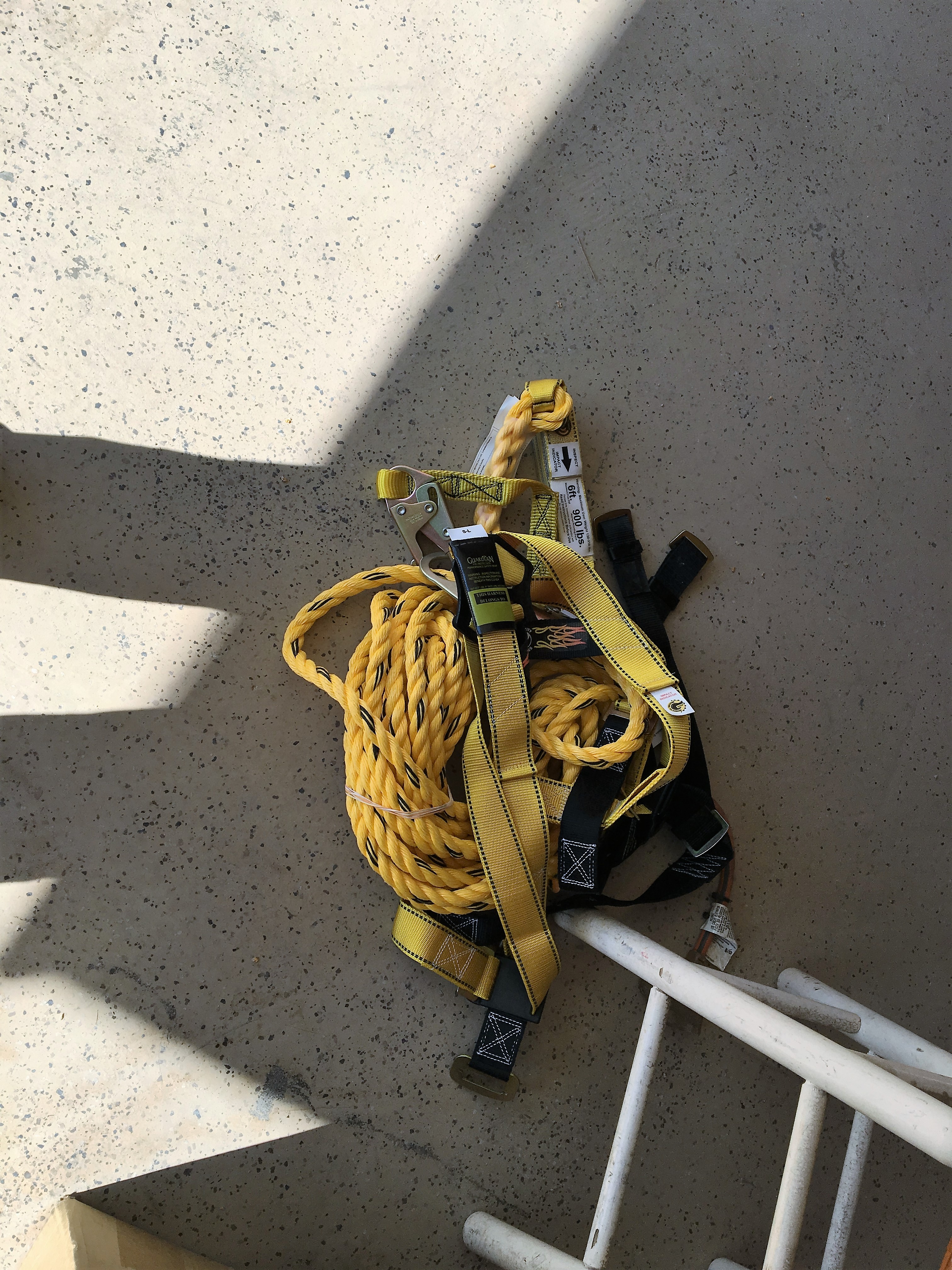
Safety harness and safety line. It’s kind of a PITA to work with, but it sure provided me peace of mind. This is what all the pros use now.

Roof safety: Roof jacks to provide a solid base for working.

Roof stripping complete. Took me all day.
Next was the trim. One might think that removing trim is no big deal. But it was to me because I had to get way up high and had to bang and lever stuff around, keep my balance while precariously perched on the scaffolding and ladder, all the while making sure that whatever fell down didn’t fall on me. The other bad news was that we were experiencing a record heat wave, so that meant that every push and pull was accompanied by beads of sweat in my eyes, lack of energy, and dehydration. I kept trying to drink as much water as I could, but there’s really no way to keep adequately hydrated while doing heavy physical labor in 96 degree heat.

Roof overhang and trim removed.
Now, on to the messy part: Knocking down the walls. This part of the demolition worried me a bit. I didn’t want to spend a lot of time cutting stucco vertically on the wall, but I needed to get the wall down in pieces that were not so big they would damage the subfloor when they would inevitably come crashing down. I first had to knock down the gable wall, first by taking down the triangular portion of the gable by splitting it at the top plate, and then taking down the vertical walls. Since the side walls are load bearing, I had to build a temporary structure to accept the load. Also, I only took down one of the side walls at a time so only one side of the roof was unsupported. Because I didn’t want to have to cut stucco while precariously balanced on a ladder from the outside, I decided to pull the wall down from the inside. Since I know that the easiest way to cut the stucco is when the stucco is lying flat, I decided to yank the whole wall down and then disassemble it. Sure enough, with all of that weight of the stucco, it came down with a big crash! This turned out to be a very bad thing because I, like a dummy, did not think to put temporary bracing under the joists of the bedroom floor. Here is the result:

Gable wall demo complete. What have I gotten myself into?

Temporary bracing to transfer the roof load to the floor. Too bad I didn’t complete the job by constructing concurrent bracing to properly transfer the load from the underlying joists to the slab foundation below.

Wall before demo.

Wall after demo.
Minor damage from the downfall of stucco. I had a surprise coming.

Joist failure as a result of not properly transferring the load to the foundation. I’m going to put a bag over my head when I call my engineer for recommendations.

Cracked joists. I needed to deal with termite damage anyway, so really no extra work. But I sure feel dumb!
Phase 2: Build the walls.
One of the tricky things about building on a second floor is that you actually have to get the building materials UP to the second floor. This meant spending the better part of a day tediously pushing lumber, mostly one piece at a time, up a ladder and onto the second floor. I had to plan ahead to make sure that I had all of the lumber for the entire build, including the interior framing and plywood, because I did NOT want to struggle hauling this stuff up the indoor stairs after I closed in.
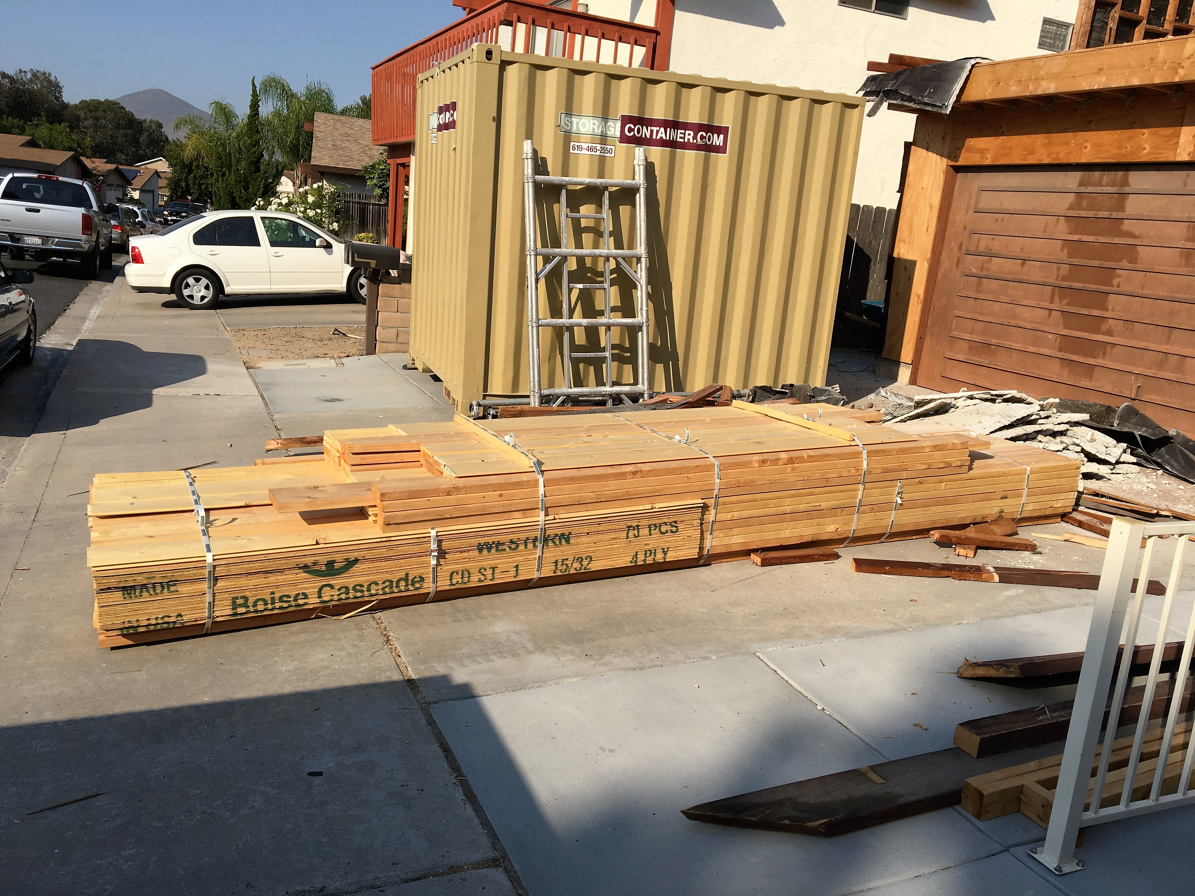
Lumber delivered. Now, to get it up to the 2nd floor!
Building a standard wall for a house is pretty straightforward. You layout and cut the lumber, build and sheath the wall while flat on the floor, and then raise it up. The easiest way is to start by carefully aligning your sole and top plates, and then doing the layout of the studs all at once. This not only saves time, but more importantly, helps to make the wall square because all of the top and bottom measurements are the same. The next thing to do is to make a “kit” for all of the framing lumber. This not only includes all of the studs, but also the headers, sills, cripple, and jack studs for the window and door openings, as well as the framing for each corner. From there, it’s a simple matter of separating the sole and top plates, scattering in the pre-cut parts, and then methodically nailing them together. It’s important to follow a nailing schedule, meaning that the prescriptive codes require specific sizes and spacing of nails for a given assembly. For example, a stud to sole plate or top plate can be two 16d nails driven longitudinally into the stud (“face nail”) or three 10d nails driven in from an angle (“toe nail”). Fortunately, the County of San Diego has a convenient summary sheet of all of these requirements, which the plans inspector “suggested” that I include as part of my building plans. I took the hint.

Wall lumber cut to length and organized to form a “kit”. I did this for the lumber for all three walls.

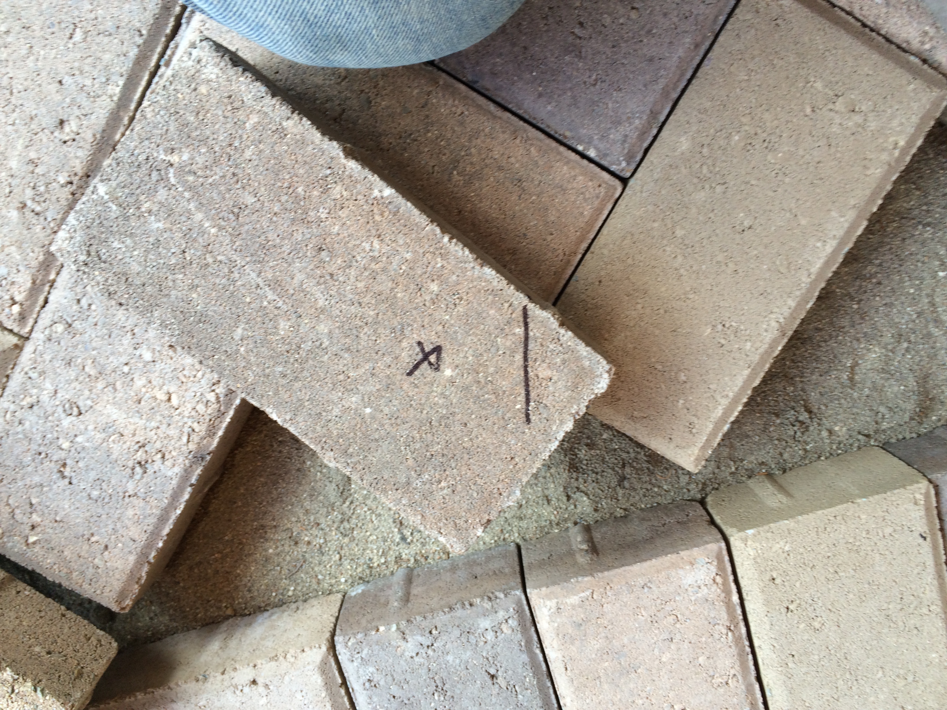
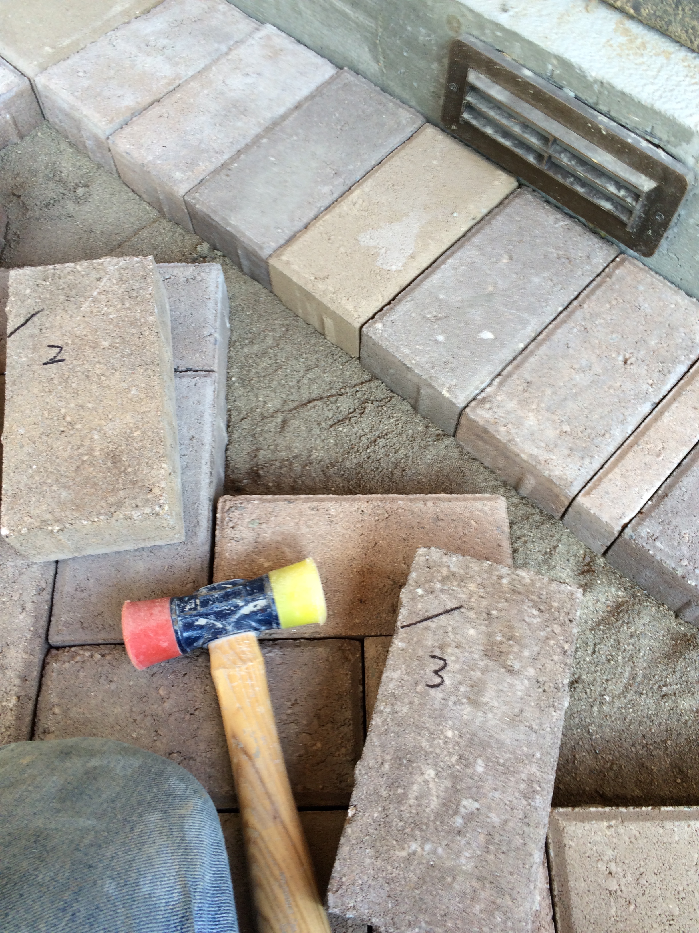
All kit parts need to be labeled so you don’t get confused. These are labeled “C/O” for “cripple” stud (window), and “outside” because the top is cut at a 5º angle to allow for water drainage from the sill.
The next thing to do is to sheath the wall. In many building situations, it’s better to put the wall sheathing on after the walls are raised because you can do some adjustments for dialing in plumb and square, and you can apply the sheathing in a fashion that overlaps the structural assemblies to add some strength. However, it’s more difficult to fool around with large pieces of sheathing, particularly plywood, when you’re trying to hang it vertically. Putting the plywood on the walls while they were still on the floor was a no-brainer for me as a one-man-show. One thing I learned about walls is that 2×4 lumber can be pretty flexible on this scale. You have to use a big sledge hammer to bang stuff around, but it’s important to square things up before you put the plywood on, because once the plywood is attached, it ain’t movin’!
Lastly the wall needs to be raised. There are lots of pictures of construction crews all gathering around a wall, and with a mighty “heave ho”, the wall comes up. Not possible with just me doing the heaving. Fortunately, there is an outfit (Qualcraft) that makes something called a wall jack. This operates much like the old-fashioned car jack that you used to hook under your bumper to change a tire. But instead of a metal jack shaft with teeth, it uses a long 2×4 piece of lumber. It’s pretty ingenious, and here is a short video and some pictures:

Wall jacks in position, ready for action!

Close-up of wall jack. 2×4 screwed into the floor prevents kick-out.

Last wall up, ready for trusses.
Phase 3: Place the trusses.
Now that the walls were up, it was time to get some help. The trusses, by themselves, are not particularly heavy, but they are difficult to handle and are fragile if they are handled while they are flat. Fortunately, the same co-workers that helped me place the big beam I needed for my garage portal were willing to spend a morning yanking these bad boys up and securing them into position. I only had 4 of these, but we had a little trial and error at first, so it took a little longer. I also had them come back to help me with the gable wall. Now, it was up to me to finish detailing the front of the roof line with outlookers and blocking.
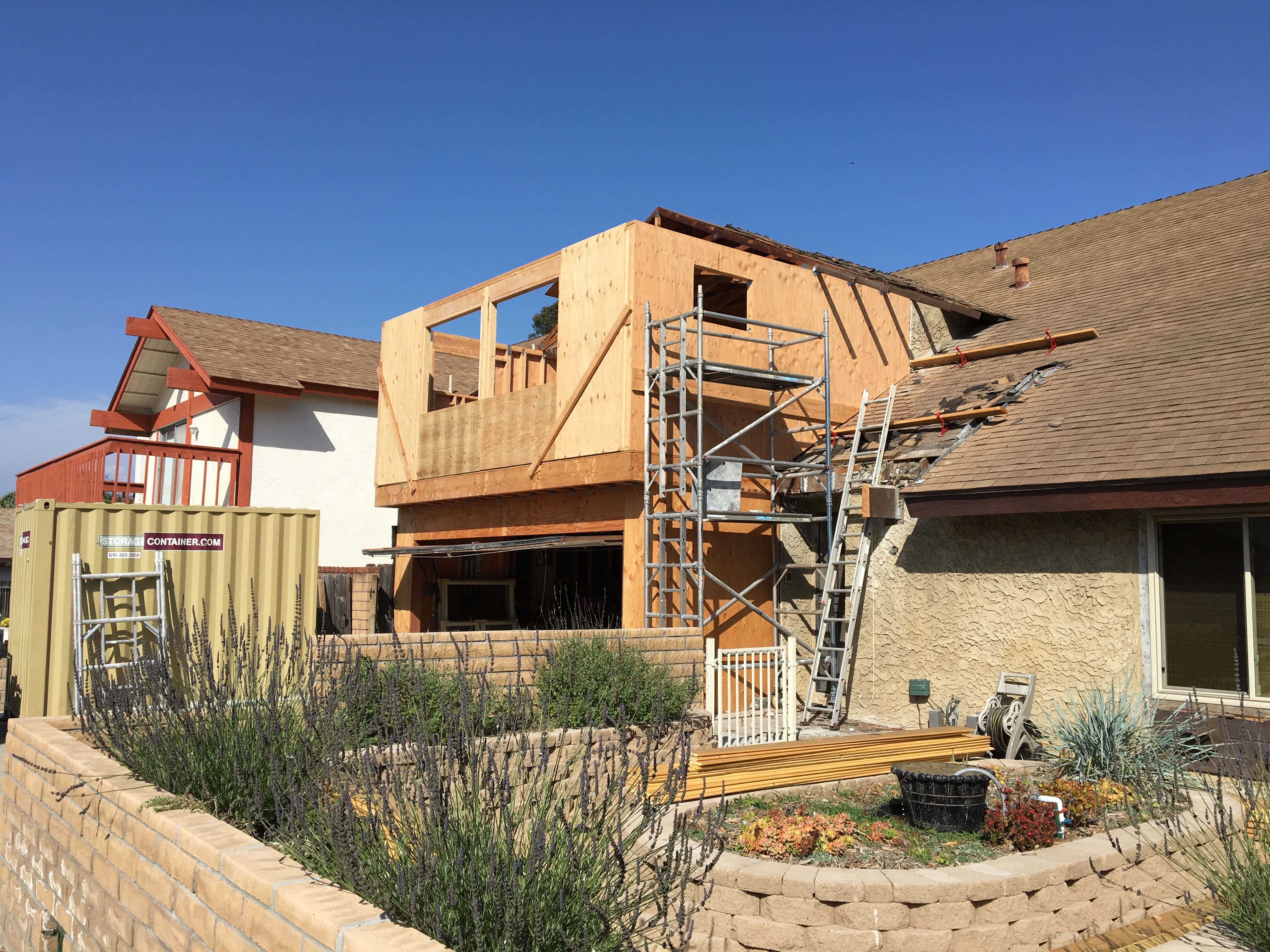
Last wall up. Things are beginning to take shape.

Trusses delivered, ready for installation.

My “crew”. Their help was indispensable in completing this phase of the project.
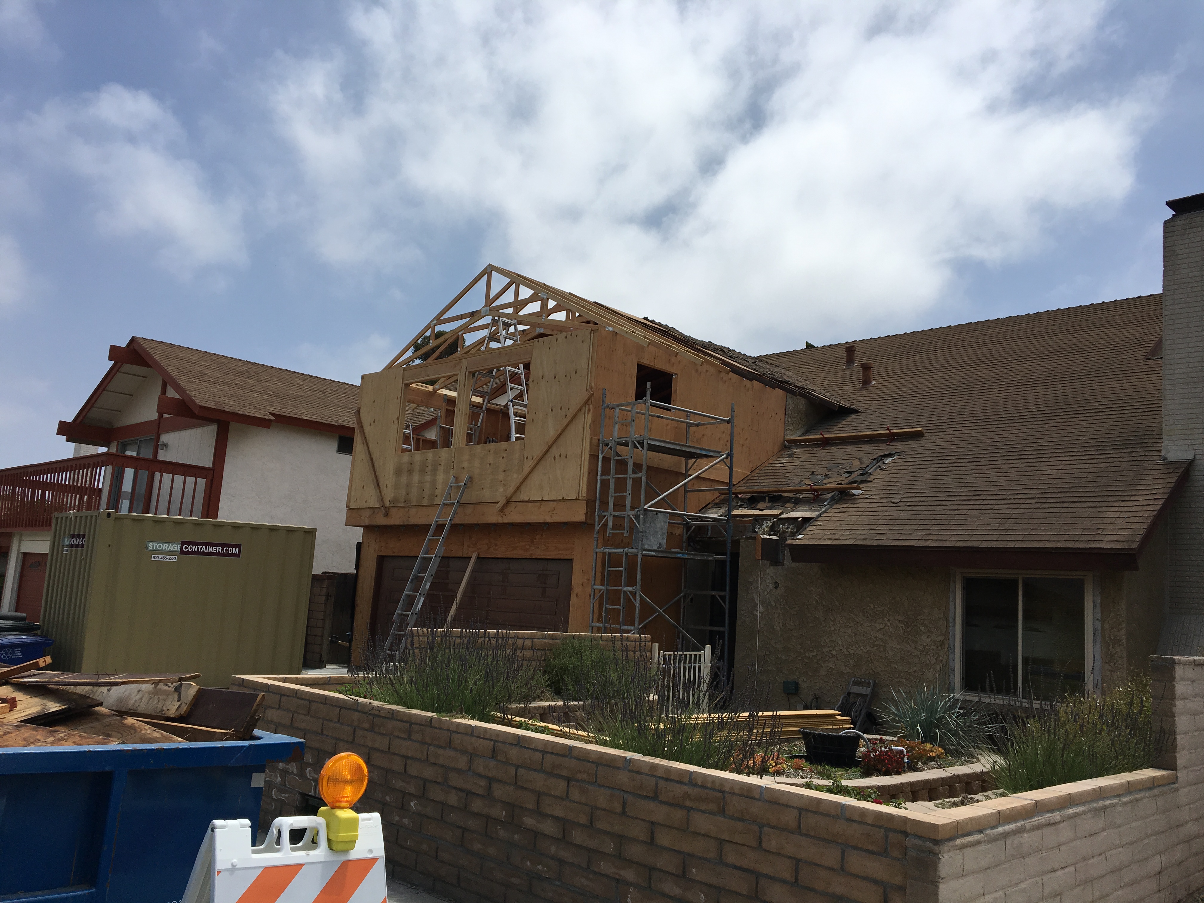
Trusses are up!

Gable wall and outlookers in place.
Phase 4: Finish the roof.
Finishing the roof was actually a two step process. I first needed to get the trim boards placed on the ends of the truss overhangs and outlookers. These are called “barge” rafters, and these were particularly long and heavy. I spent an entire day messing around with scaffolding and engineering a “third hand” to hold the rafter while I put it in place. But when I found it impossible to even the the board up there by myself, I knew it was time to call my crew back for another session. Sure enough, in about 3 hours, we were all done. Finally, I was able to get the roof sheathing in place. If this were a flat surface, this job should have taken about 3 hours. But because it was on a roof, I had to laboriously move around and reconfigure scaffolding, haul materials up and install them, and then move onto the next part. Getting the plywood up for the roof sheathing was also challenging. I decided to make a simple lifting fixture from scrap 2x4s that I screwed onto the plywood, and then used a rope to pull up the plywood. I also set up a couple of long boards to help the plywood slide up to the roof. This lifting fixture also proved valuable in placing the plywood because it gave me some leverage. Note that I had to place on piece of plywood at a time using this method, so, again it took a long time.
Another thing I learned about working on a roof is that it’s physically hard! That’s because you constantly have to fight against gravity because you’re working on a slope. Plus, there’s no shade (duh!). So, in addition to it being hot, all of that up-and-down and muscling the plywood in place really wore me out. In the end it took about a week (!) to finish the roof. But I liked the result.
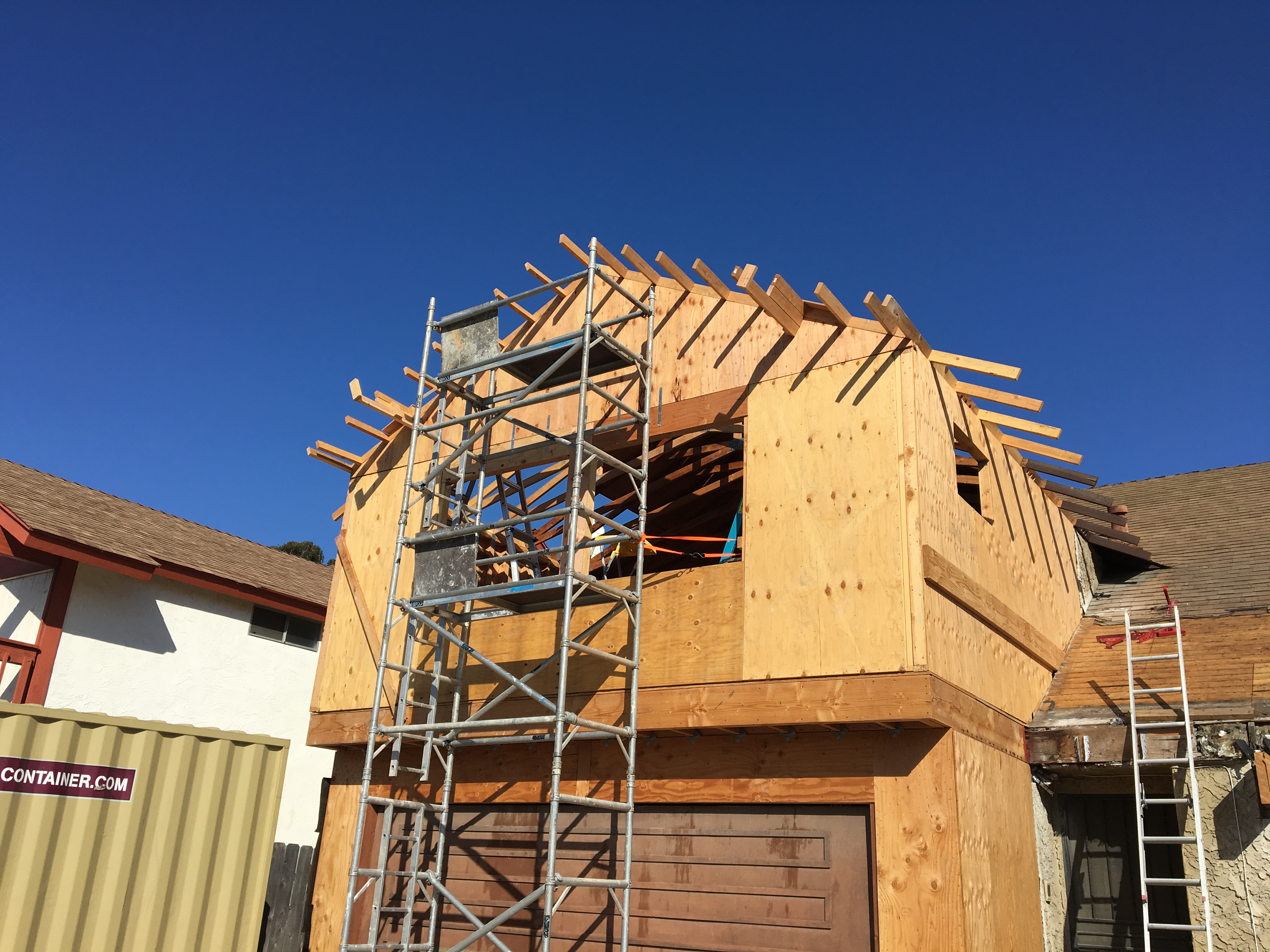
Outlookers in place, ready for the barge rafters. Note the “3rd hands” to the right and left of the scaffolding on the outlookers.

Barge rafters in place. Beginning to look like a house!
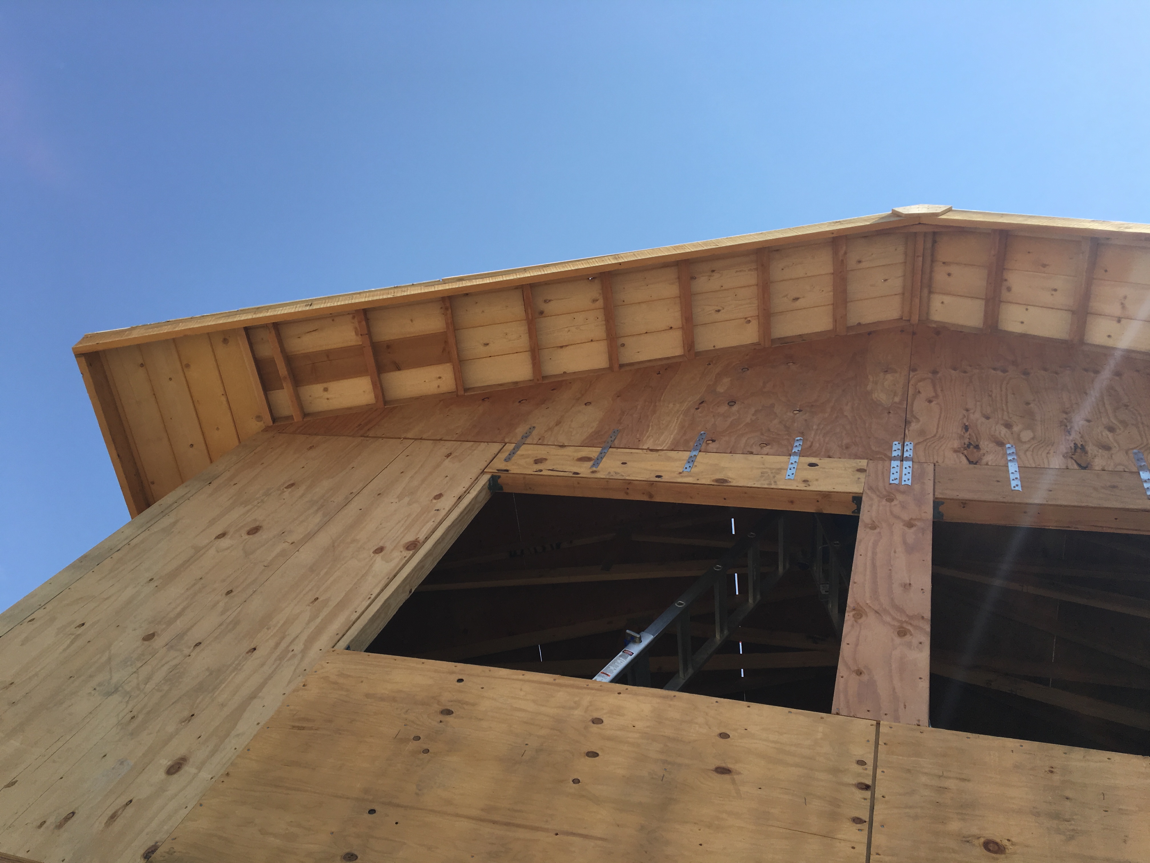
Shiplap appearance boards are on the roof overhangs to match the rest of the house.

Roof all done! Looks nice.

The inside. This is going to be a nice bedroom!

The proud builder and his creation.
Phase 5: Install the connectors.
Actually, installing the connectors is something that I did as I went, but I wanted to highlight the fact that the days are gone when you can simply use nails to build a house. Modern house construction uses metal connectors almost everywhere, especially between major components (e.g., foundation to first floor, first floor to second floor, second floor to roof). There are hundreds of connectors to choose from, but that was taken care of during the design phase, so the ones that I’m using are all in my plans. Each connector has a specific fastening schedule (number and type of fasteners), so you have to be pretty meticulous. I made copies of the specification sheets for each connector that I used, and highlighted each one and keep them in my permit book so that when the inspector comes by, I can show him what I’m working to. I really did learn something when I prepared for my inspections in the Navy!
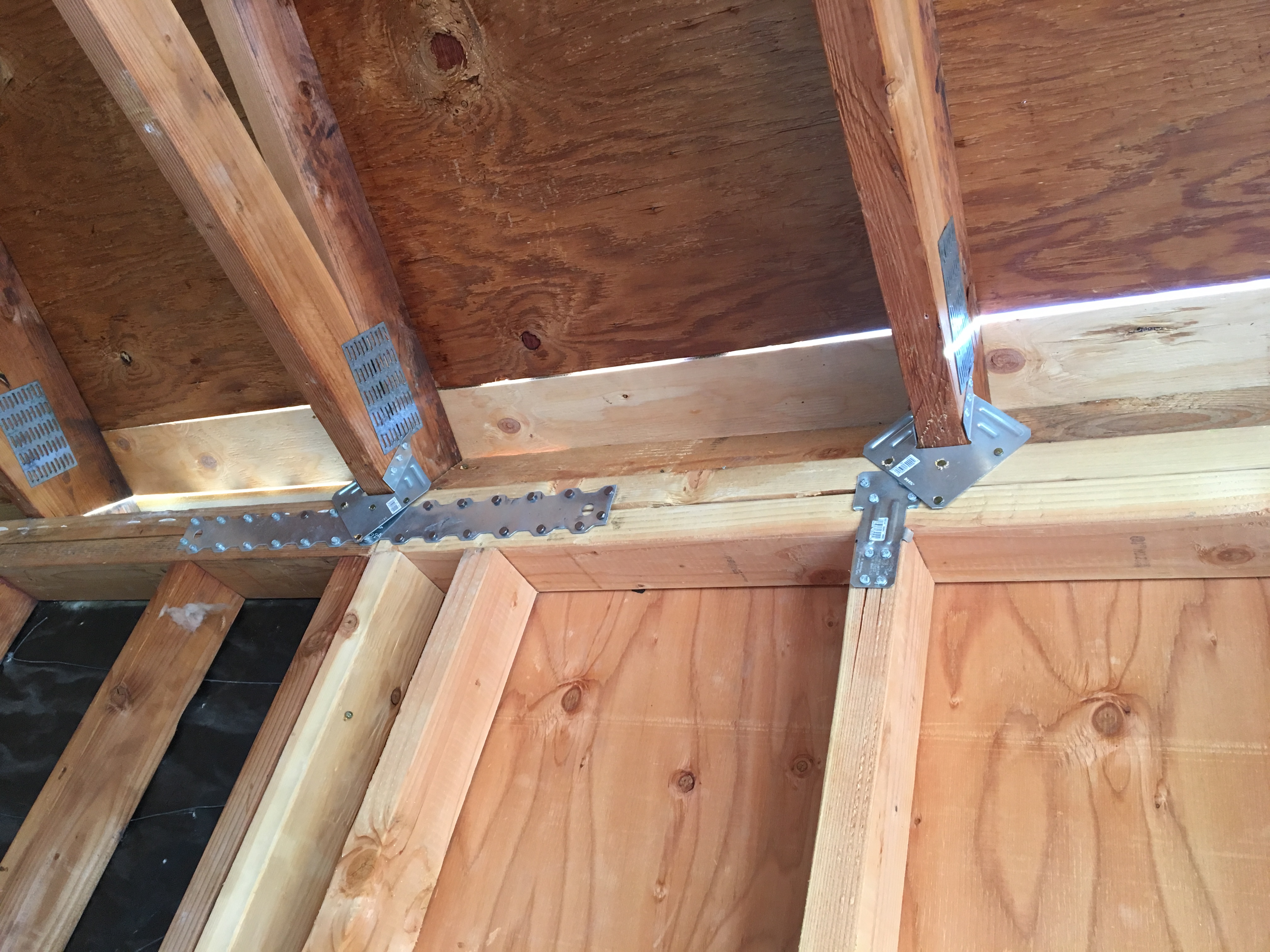
Metal connectors for the roof, studs, and top plate.

Connectors between gable and front wall. I still need to add connectors between the wall and the rim joist on the bottom.
I’m hoping the pace will now pick up with the roof, windows, stucco, and HVAC contractors coming in. Stay tuned!