In and amongst the holidays, I was able to wrap up the outside work so I could go into the New Year with a clean slate and start on the OTHER part of the remodeling project — the INSIDE!! The good thing about finishing up was that the work could be easily broken up into short stints so it was relatively easy to fit this remaining effort into a busy holiday schedule.
First on the list was completion of the drip irrigation system. I bought all of the parts over a year ago, because I had to install a bunch of stuff underground, so what is shown in the photos has been gathering sawdust in my garage for over a year. Maybe that wasn’t the smartest thing to do because a few things changed during construction of the planters and retaining walls, so I ended up overbuying some things, but I definitely wanted to get all the parts from the same manufacturer (Rain Bird) to make sure that they all fit and worked together. I have a previous post on the design of the irrigation system if you’re interested.

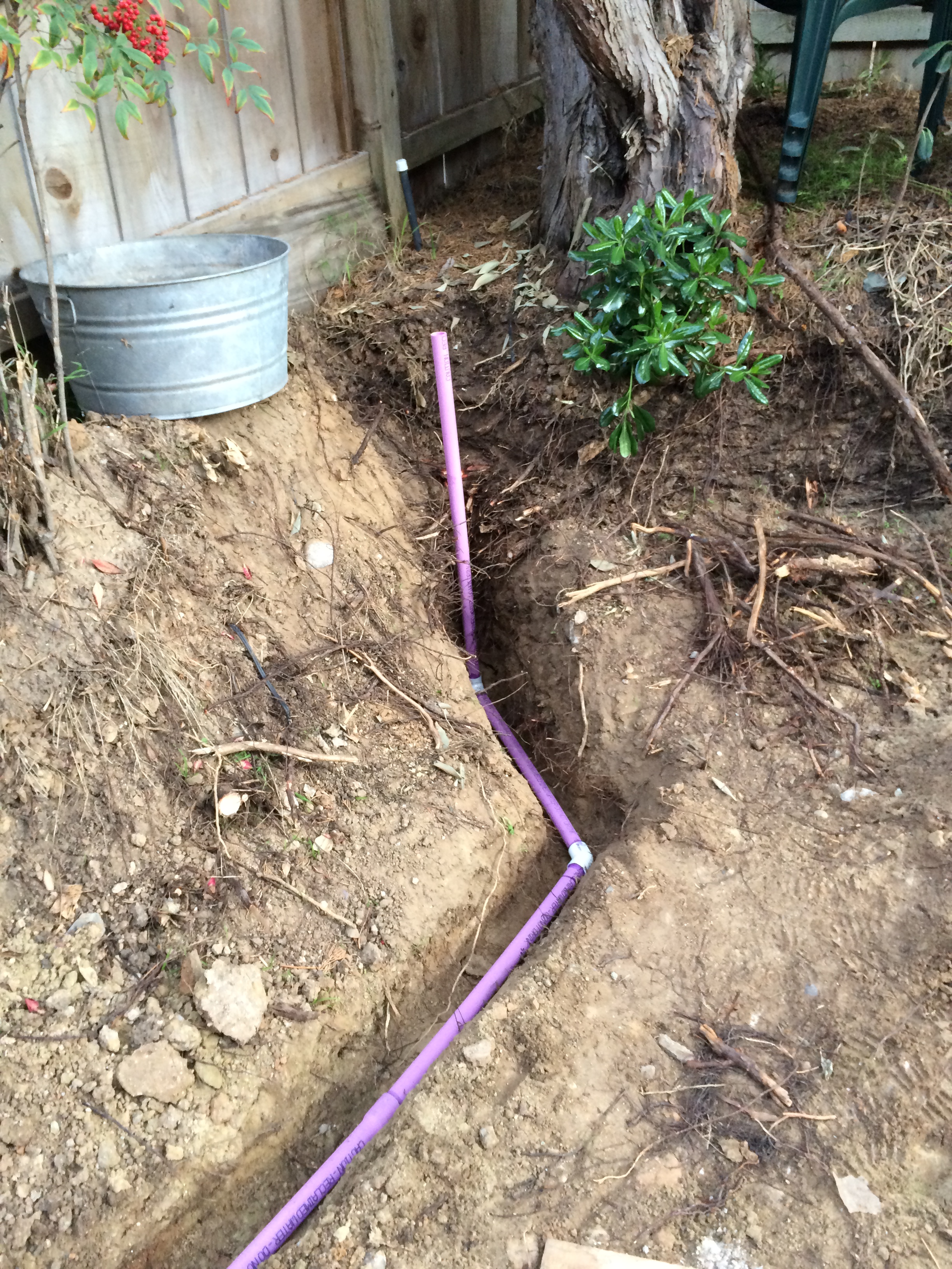
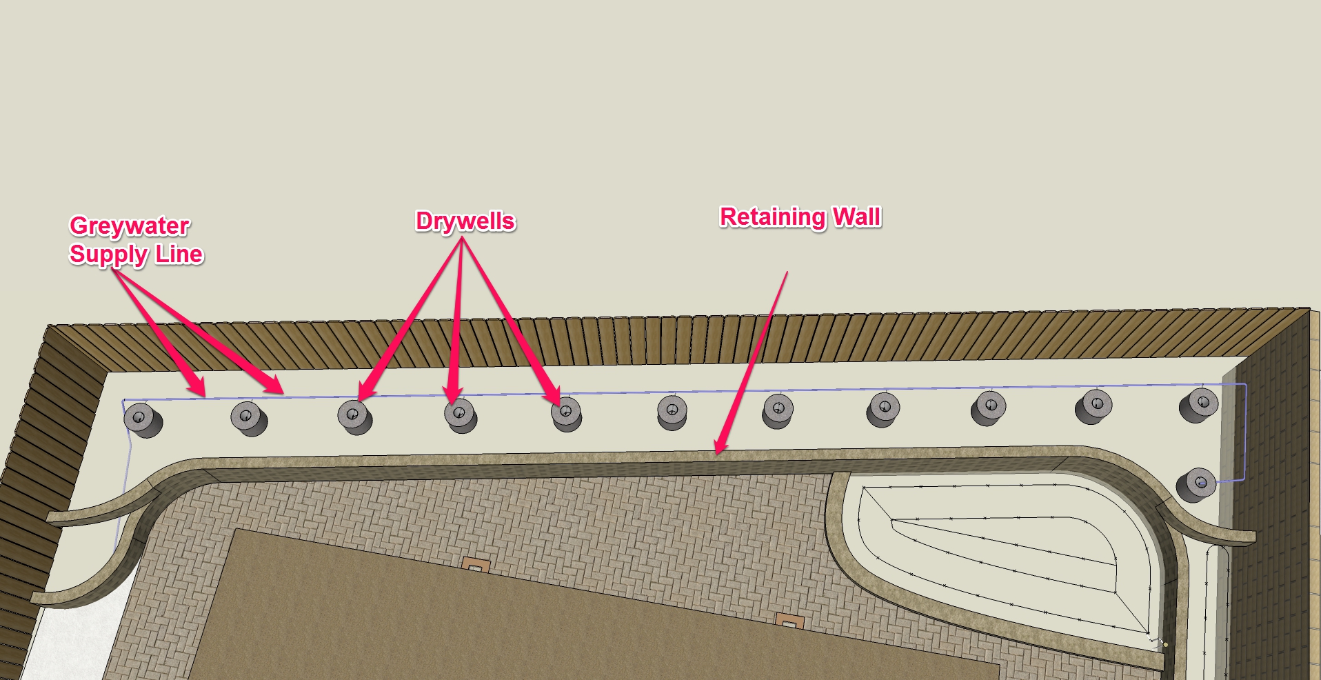
Irrigation plan details. The laundry greywater (purple) is already installed and all of the underground pipes and control wires are buried and ready for hook-up.
The first thing that I needed to do was to hook up the wiring. This is not terribly difficult to do, but you do have to keep track of which wires are doing what. In my case, I have a total of 5 zones, which means 5 valves, plus a rain sensor. Each valve requires one dedicated wire, and another connection to a common wire, which makes 6. The rain sensor requires 2 wires, so that’s a total of 8 wires. Plus, you always want a spare or two, so I ended up getting a 10 wire control cable. Now comes the important part: WRITE DOWN what color goes where, and then COPY that to someplace that you will remember. Most folks just write it down on some sort of sticker that they put on the inside of the irrigation controller door, but because mine is going to be part of a smart home and connected to the home controller via ethernet, it won’t have a door, so I’ll have to figure out something else.

This is my plan for mapping the irrigation zone numbers to the wire colors. I sure hope I remember to put this somewhere where I won’t forget about it or throw it away!
Connecting the wires is pretty simple. The wires are fairly small (18 gauge), so you’ll need a wire stripper that accommodates the smaller size. I found out this the hard way years ago, so I now have two wire strippers that cover most all sizes between the two of them. Don’t be all cheap and use a knife to strip the wires. You’ll damage the wires, AND your fingers.

Types of wire cutters. The one on the right is pretty common, but I’ve always had trouble with it. I bought the others which are specifically designed for stripping wire (and nothing else). The one on the left is mostly used for residential wiring (which includes the irrigation control wires). The one in the middle is what I use for wiring electronics (smaller wires).
The way to properly join the wires together is with waterproof wire nuts. They work just like regular wire nuts, but they are stuffed with petroleum jelly (Vaseline) and have a flexible retainer on the bottom that holds the goop inside. You’ll want to get the smallest ones. If in doubt, the package will have the number and combinations of wire sizes that you can use with that particular size of wire nut, so you should be able to figure out what you’ll need. Turns out that the sublime skill of choosing the correct wire nut is vastly more important when working with standard residential electrical circuits (120v/240v), so it is a must-learn for the serious do-it-yourselfer.

Tools for the wiring hookup. From left to right, you have the waterproof wire nuts, a set of “dikes”, wire stripper, needle nose pliers, and a utility knife.
Now that you have the right tools and materials, it’s pretty straightforward to hook everything up. You’ll have to “daisy-chain” the common wire, meaning that you’ll take the incoming white wire, outgoing white wire, and valve wire and twist all three together, and then go to the next one, etc.. Just remember to follow the color codes that you made up earlier. One quick note about the valve wires: it doesn’t matter which one you choose to be hooked to the common (white) wire and which you choose to hook up to the individual colored wire. That’s because the valves work on 12v alternating current (AC). Since it’s low voltage (i.e., cannot cause a fire or deadly shock), there aren’t any complicated rules about neutrals or grounds, so, bottom line, it’s pretty hard to f*** up. One other thing about electrical wiring is that it pays to be neat. Sure, if the electrical connections are correct, the darned thing will work, but making things neat and secure will not only make it much easier to troubleshoot and repair when (not if) it is necessary, but will also make those repairs LESS necessary. Plus, you want to have pride in your work, yes?
To get to the wires, you’ll need to strip off the sheathing. This stuff is a bear to get off, but there’s a trick. Use a utility knife and make a small slit in the sheathing and then pull it back. Find the white thread and give it a pull with pliers down the sheathing. Voliá! The inner wires are nicely accessible. Strip off about 1″ from each of the wires you want to join, and then twist them together. You want them to match up where the insulation ends. Don’t worry about the ends, as they will be cut off. For this size of wire and wire nut, 1″ is way to long, so use a set of diagonal pliers (“dikes”) to cut the twisted wires to the correct length (about 1/2″). This allows you to insert the wires well into the wire nut, and you want the goop to cover the wires all the way past the insulation to fully waterproof the connection. Twist the nut until you feel it “bite” the wires, and then continue twisting 1-2 turns. The wires coming out of the wire nut will twist around each other, and this provides assurance that the connection inside is nice and secure while also providing some mechanical strength to the assembly. When you have all of the connections made up for the valve, use a nylon tie wrap to secure everything together. Nice and neat! Here are some pictures:

Cut the sheath of the control wire cable with a utility knife. All you need to do is to get it started. Since you might damage the control wires when you do this, allow sufficient slack so that you can cut this end off after you strip the sheath.

This is a little thread that can be used to strip the cable sheathing. It is pretty difficult to grab with your fingers, so I found using needle nose pliers pretty much essential.
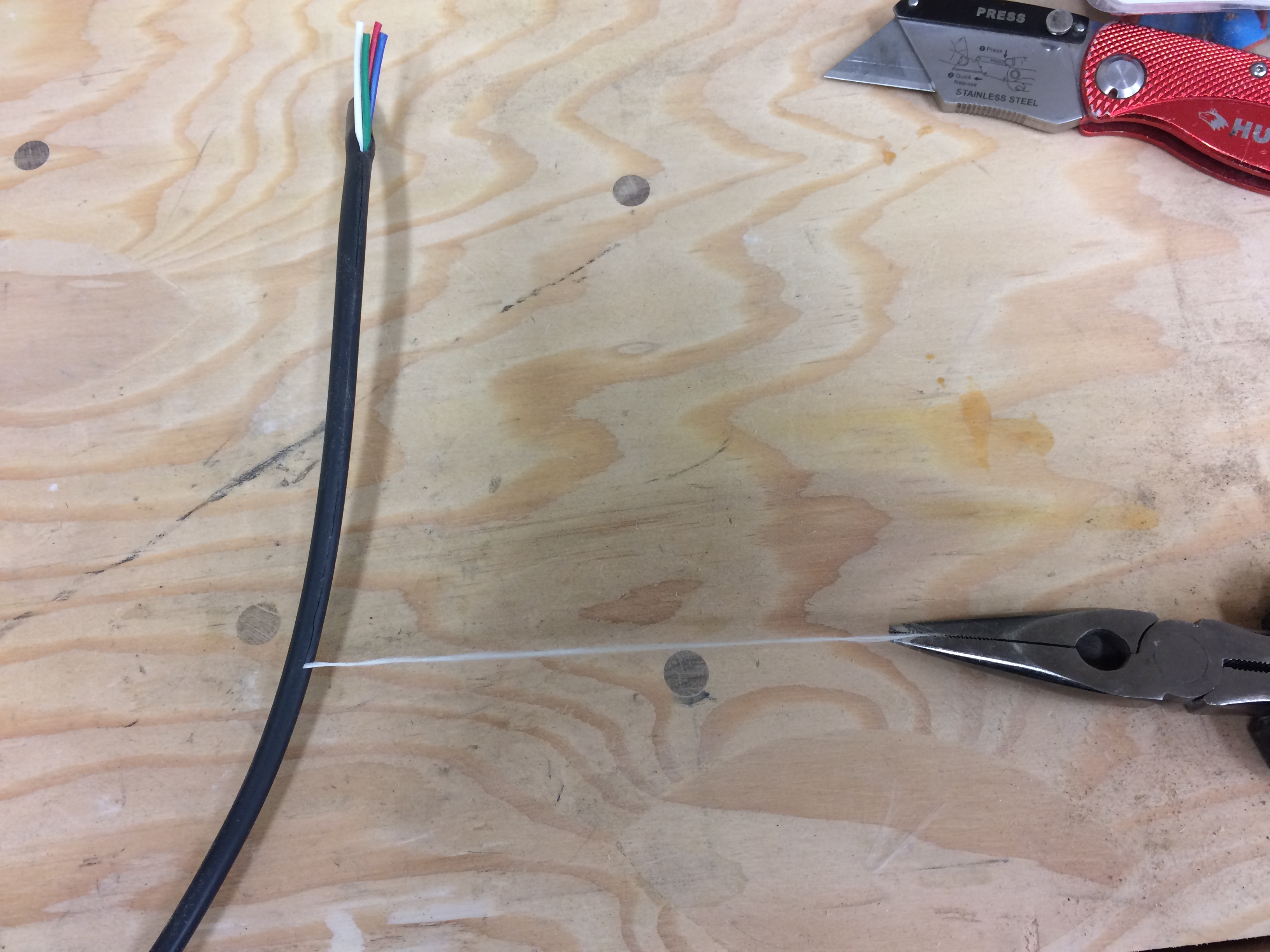
The white line does a really good job of cutting through the sheathing. You’ll want to cut a fair amount of sheathing off to give you plenty of wire to work with. You did remember to allow lots of extra cable during the underground installation, didn’t you?

The wire stripper will have several holes, each marked with the gauge of wire that you’re stripping. Find the number that corresponds to the wire you’re working with (in this instance, 18 gauge) and then squeeze the handles and pull off the insulation.

To twist the wire, line up the wires at the ends of the insulation and then twist clockwise.

Wires all twisted together and ready for the wire nut. Well, almost….

Twisted wires are too long for the wire nut. This is on purpose.

Wire is now cut to the proper size. I do this because (a) I want to make it easy to twist the wires together, and that means they will be too long, (b) cutting gives a clean end with all wires at the same length, and (c) The wire ends have little sharp edges which will give a good “bite” into the spring insert of the wire nut when you screw it on.

Wire nut properly twisted on. Note that the insulation of the wires goes up into the base of the nut and that the wires are twisted around each other, ensuring a good mechanical connection.

Here is an example of a completed wire assembly for an irrigation control valve. The white wire is the common wire, and the green wire is the color that you used per your plan. You have a plan, right?

Control wires in the farthest valve box. I initially used electrical tape to group the wires together but decided that it was (a) kind of difficult to be neat and (b) will be tough to take apart if I ever have to. Nylon tie wraps are better.

Control connections completed in the front. Lots of wires, but all are grouped neatly and out of the way of the manual controls.
Enough about the electrical stuff. Let’s get to the irrigation! Drip irrigation is simple on the one hand, and nuanced on the other. A basic drip system is composed of a drip supply line (dripline) and drippers (emitters). The dripline is typically a 1/2″ thin-walled polyethylene piping, which is fairly flexible (when warm) and elastic. This flexibility will allow you to “punch in” the emitters with a special tool (yes, you need the special tool!) wherever you need them. The emitters have a sharp barb which, when pressed hard against the drip tubing, will pierce it, and the tubing will self-seal around the barb because of the aforementioned elasticity. And there you have it: a dripper ready for action! (Note that there are many different kind of drip emitters. If you want to learn more, you can go to the “Irrigation Tutorials” website to find out more. BTW, this is a GREAT site if you want to really learn something about irrigation!)

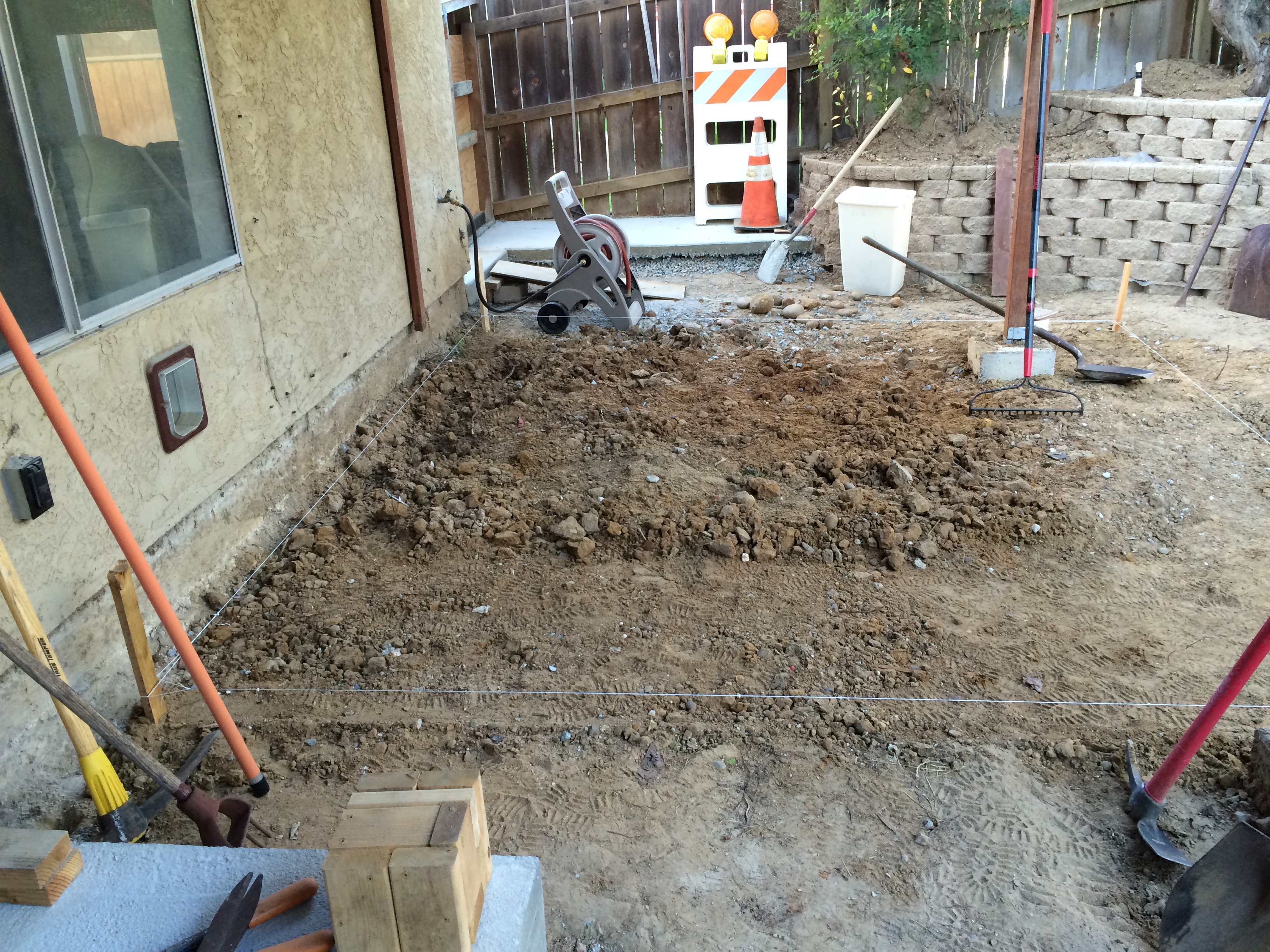
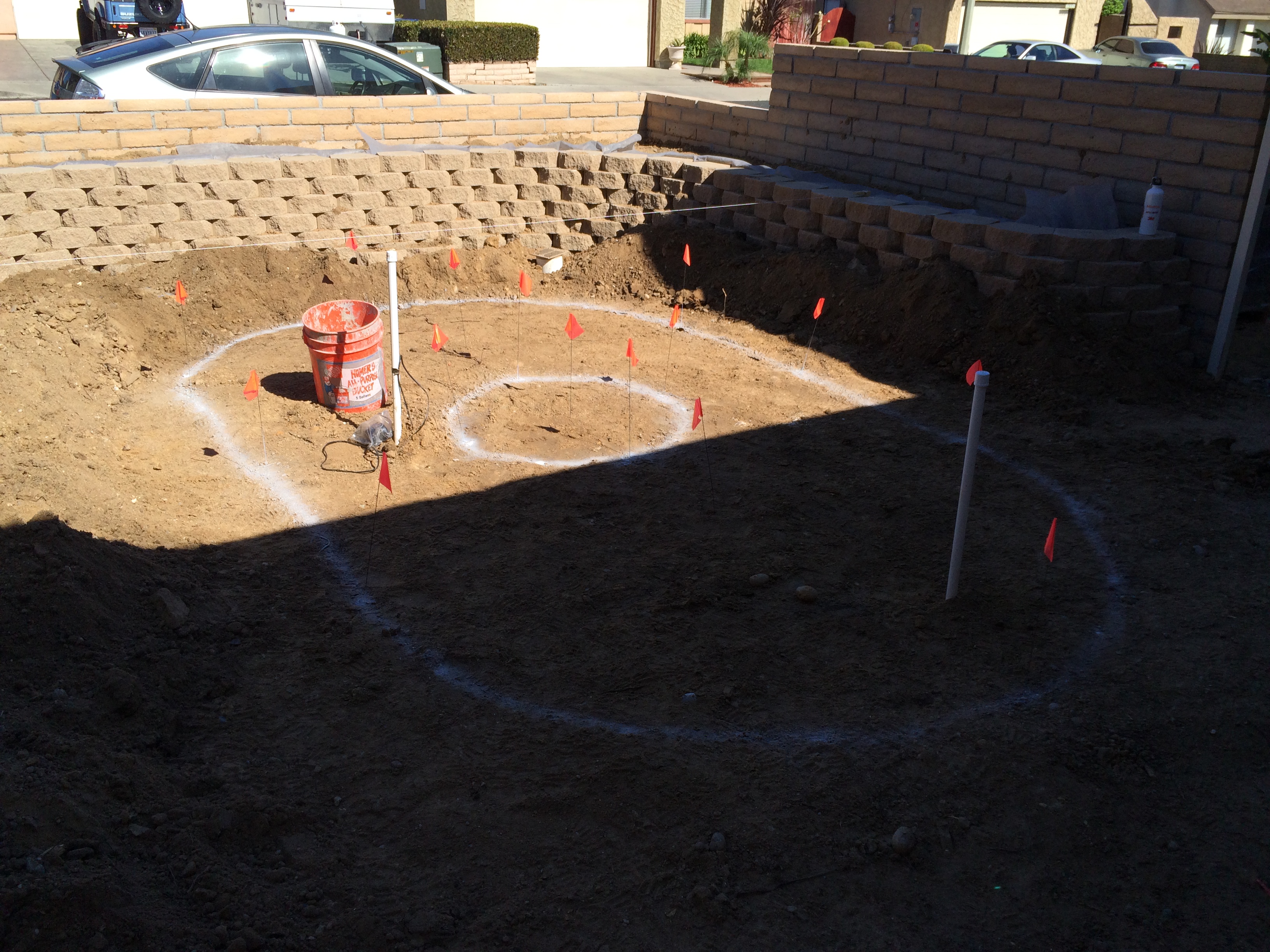
Ready for installation of the driplines and emitters. I’ve had these parts for about a year, so it’s time to get to work!
Now comes the nuance. Where do you need to place the drippers? Again, the Irrigation tutorial website gives excellent advice on emitter spacing. It also shows you how to do a simple test to determine the optimum spacing. I did this test and determined that the optimum spacing for my soil was 18″. That meant the each dripper needed to be 18″ from the adjacent ones, and the dripper tubes needed to be 9″ from the edges of the planters, and 18″ between each dripper line.
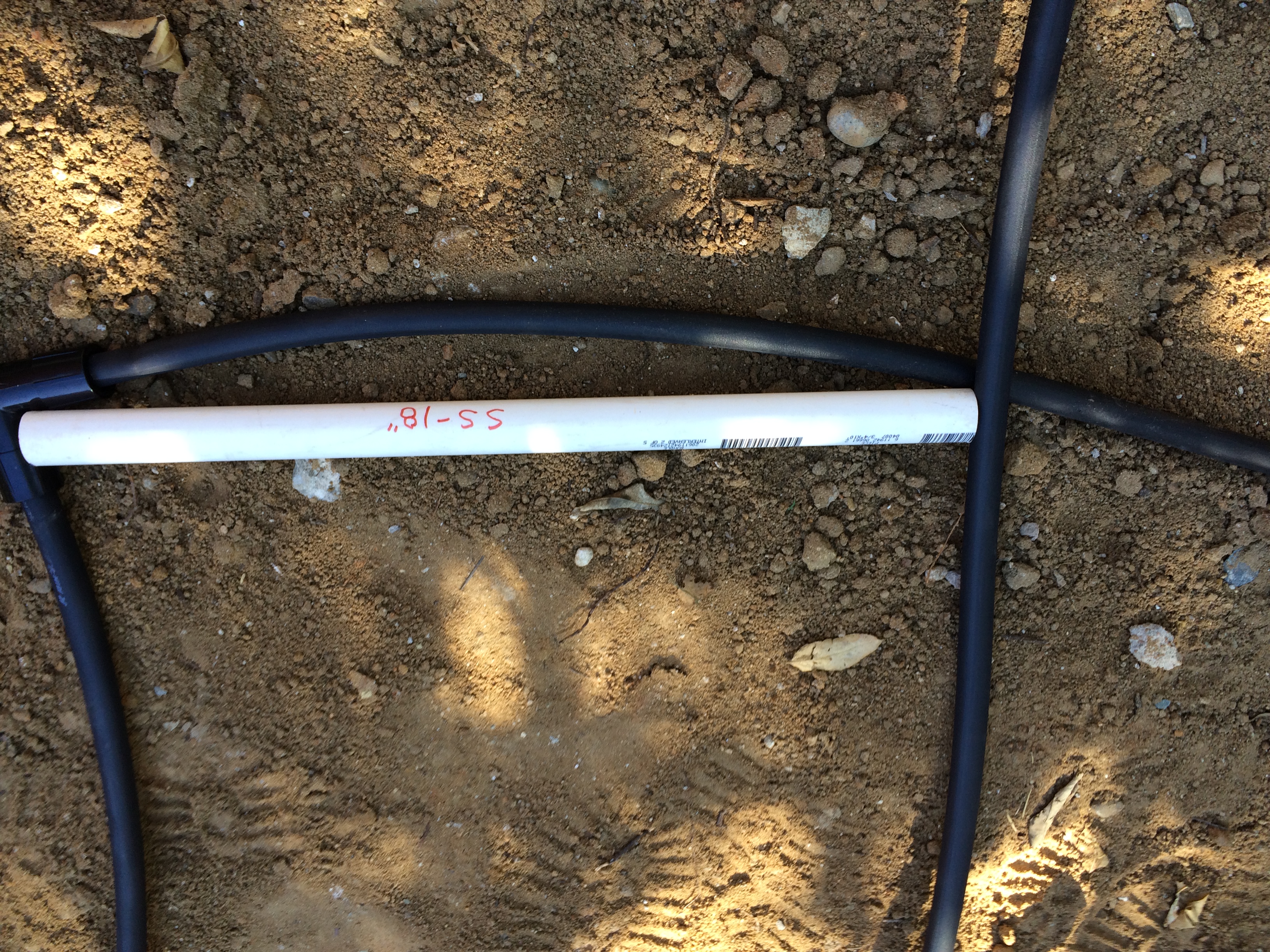
An 18″ spacer stick made from scrap PVC pipe. I used this to space my dripper lines and emitters based on testing that I did earlier.
With those details out of the way, I was ready to start actual work. Remember how the irrigation lines were installed in the trenches way back when? Well, the have some dirt inside due to the nature of the assembly process. So, the dirt must be flushed out first, otherwise, you have a bunch of emitters that will get clogged and won’t work. With some trepidation, I turned on the water supply to the irrigation system, and thankfully there were no leaks or blowouts. Not that I expected any, but I’ve been proven wrong before. I then used the manual override on each control valve to thoroughly flush out the piping. I then installed the mandatory vacuum breaker assembly on each of the stubs, and then was ready to connect the dripline. The best way to connect dripline is with compression fittings. These can be a little difficult to work when it’s cold (as it was the day I was doing the installation), but with enough twisting, pushing and swearing, the damn things will go together. Being mindful of the spacing requirements, I laid out the dripline on the ground and used U-shaped stakes (made for the purpose) to hold everything in place. The dripline comes in big coils, so it’s best to try to warm it up in the sun beforehand so it becomes more flexible.

Above ground drip irrigation parts.

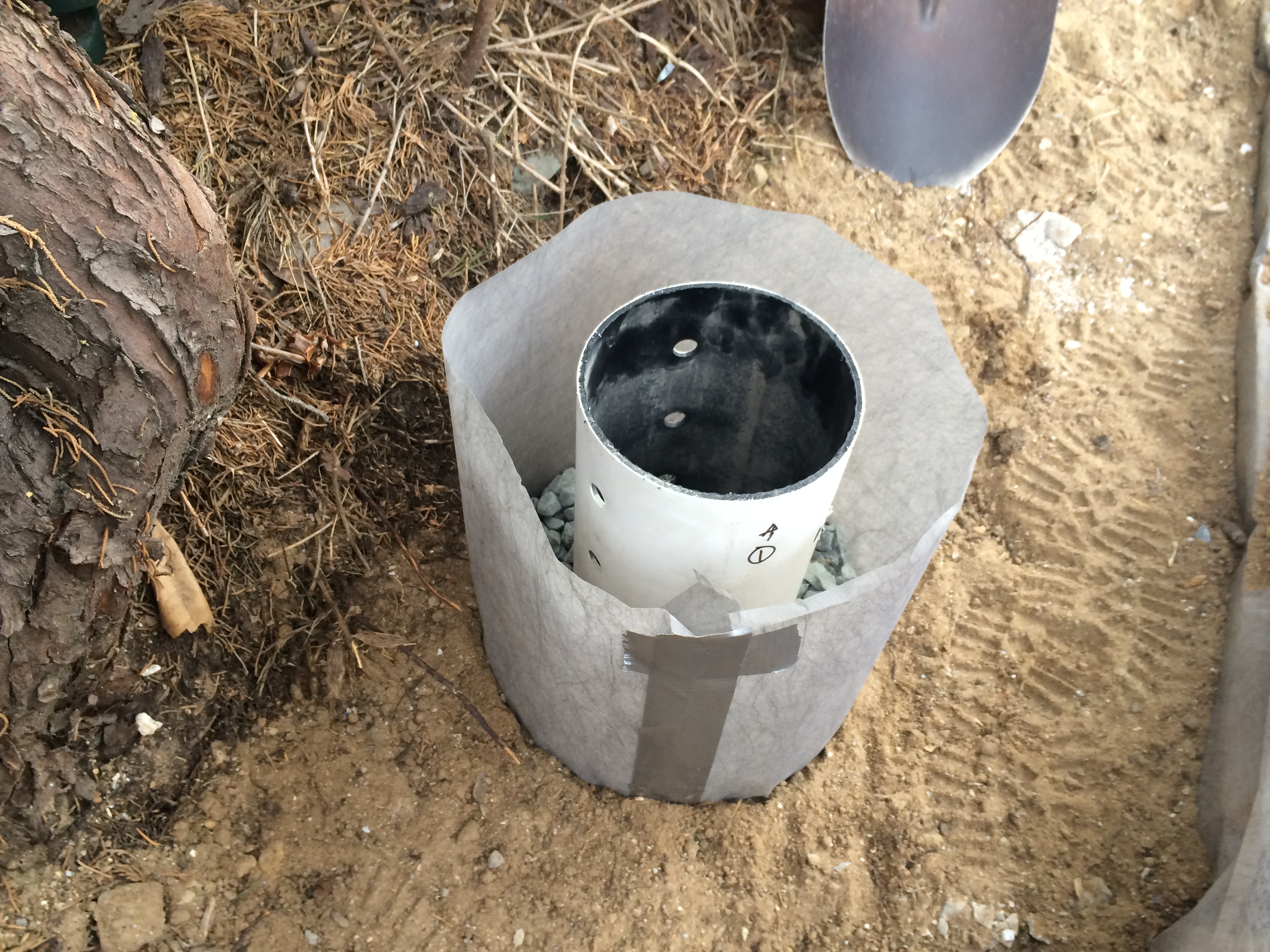
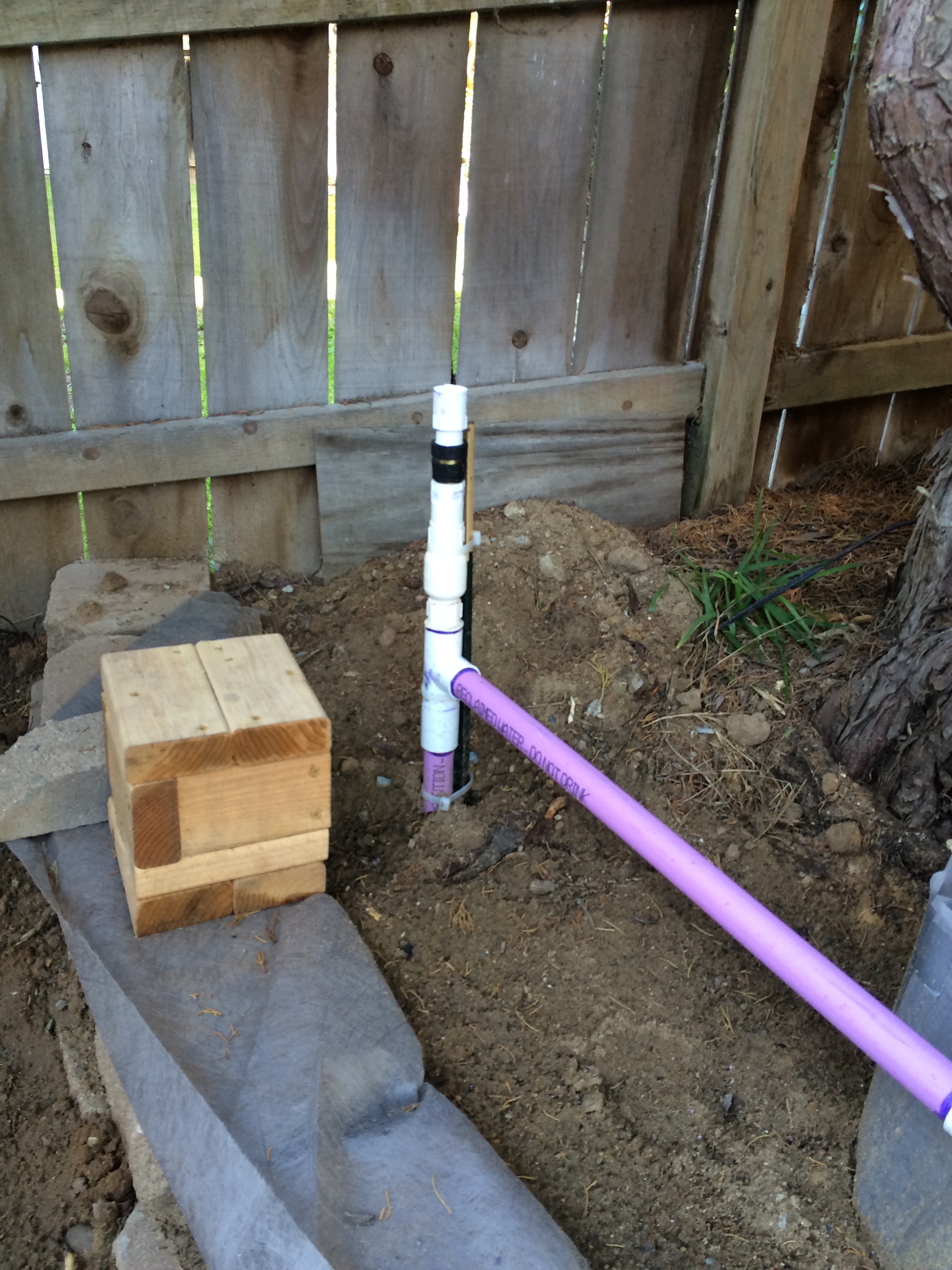
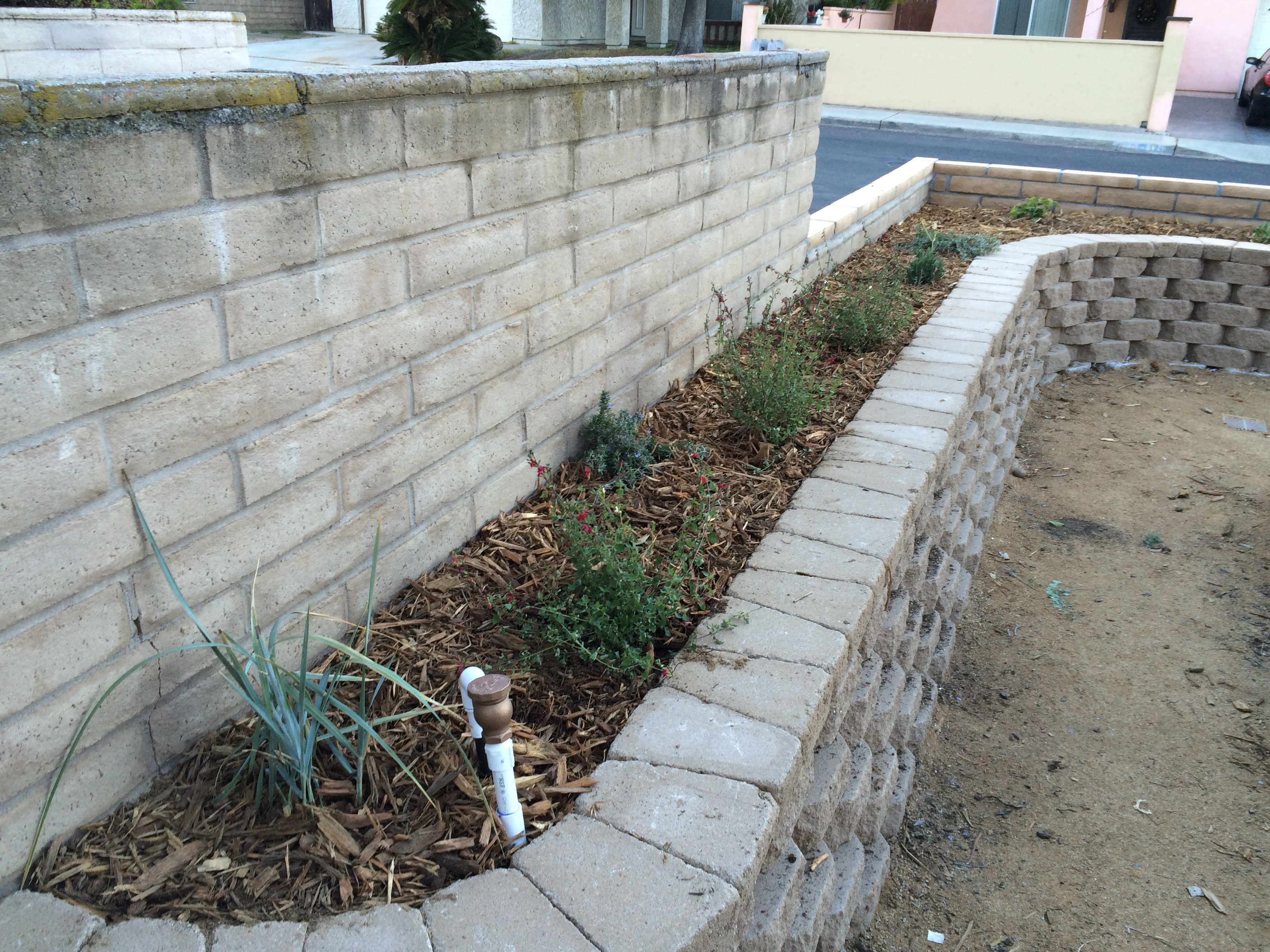
This is what is known as an Atmospheric Vacuum Breaker (AVB). This must be installed at least 6″ above the highest point of the associated dripper line so that you don’t get backflow into your drinking water. We have an outdoor cat, and who knows where he goes or what he does. All I know is that I occasionally find some of his “nuggets” well hidden under the mulch. Best not to take any chances!

Getting my driplines warmed up by the sun so they will be more workable.

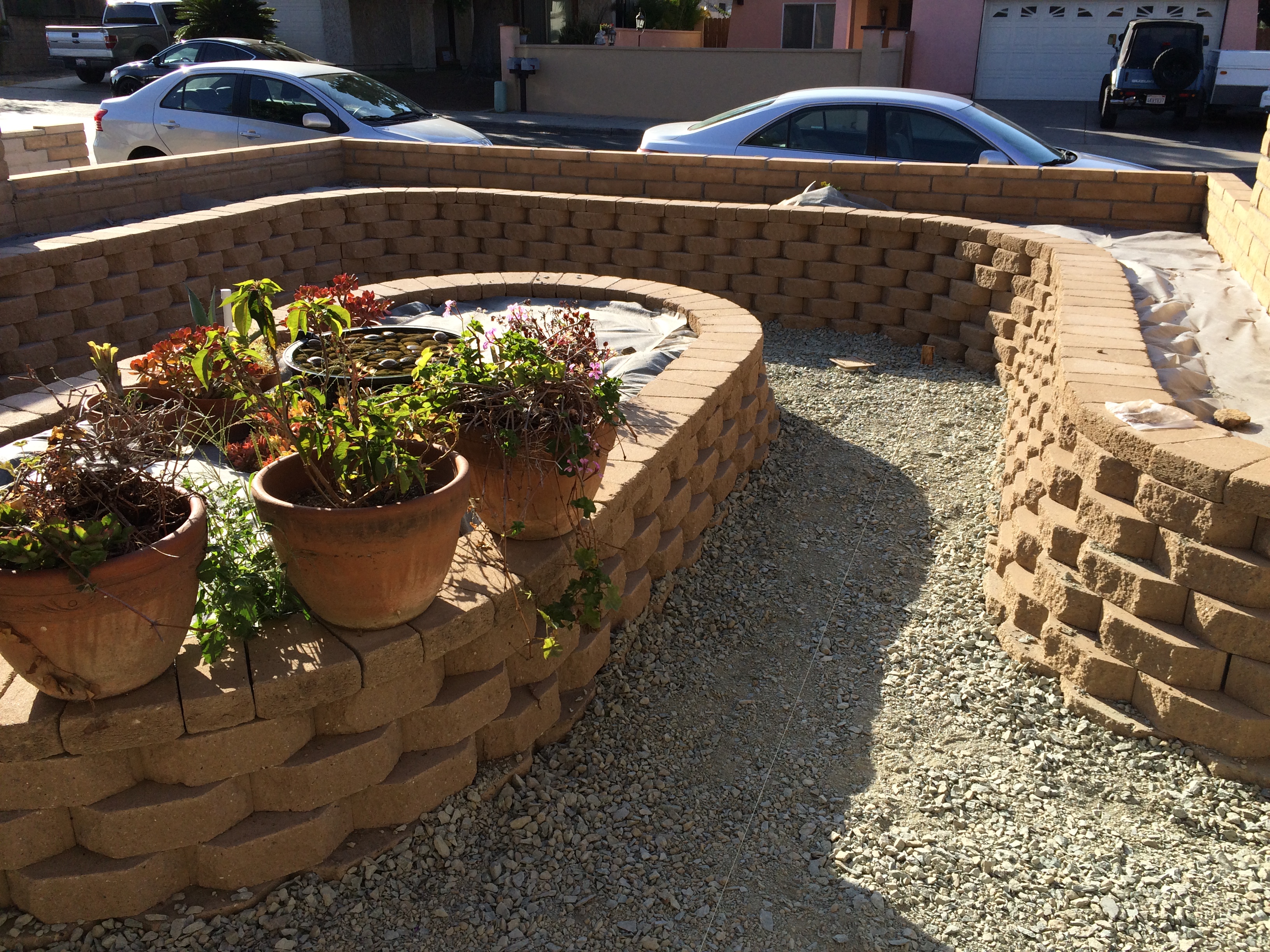
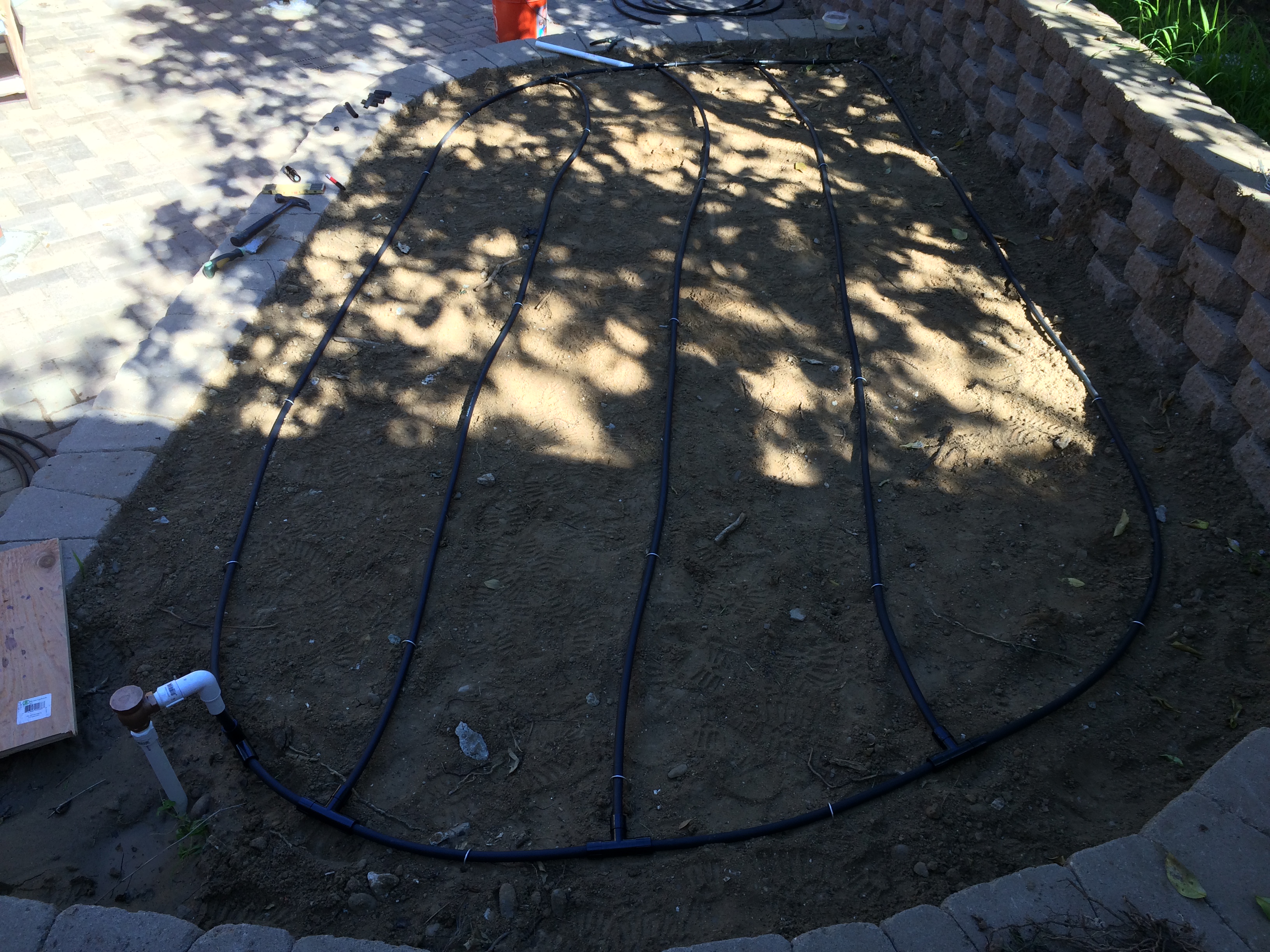
Front planter driplines all connected and staked.

The side yard with dripline installed.
Dripper lines in the herb garden. Because I want flexibility in this area, I chose to run the lines at a 18″ spacing and do the same with the emitters. That way the entire area will be irrigated.
One of the important design considerations in a drip system is to provide a means of flushing the driplines. This will typically be a stub off the farthest end of the line (or a tee if the line is looped) that has a removable plug (that you bought in anticipation of this need). So before you begin in earnest to install the emitters, you’ll need to perform a good flush of the dripline that you just installed by removing the plug and manually activating the irrigation zone of interest.
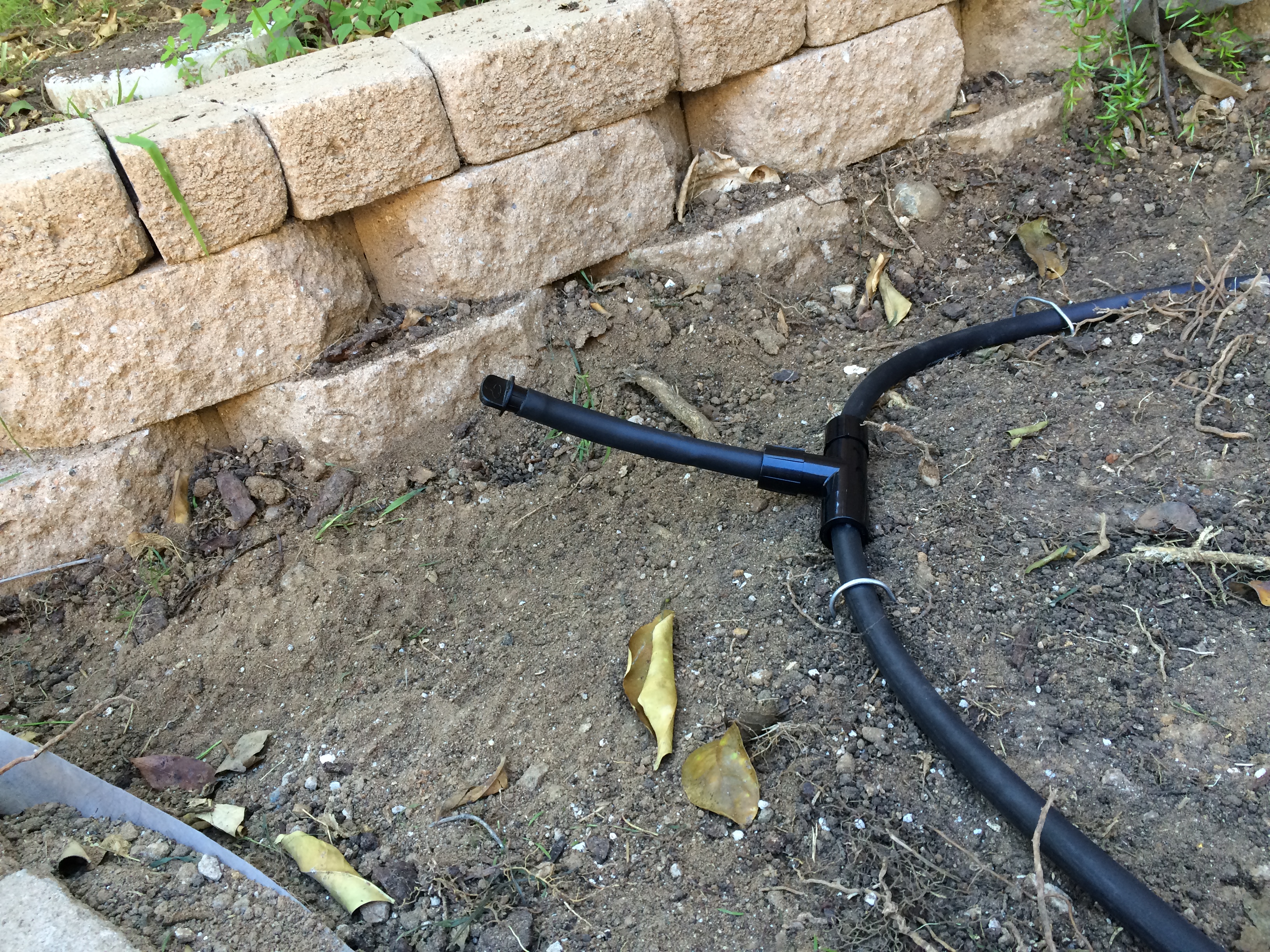
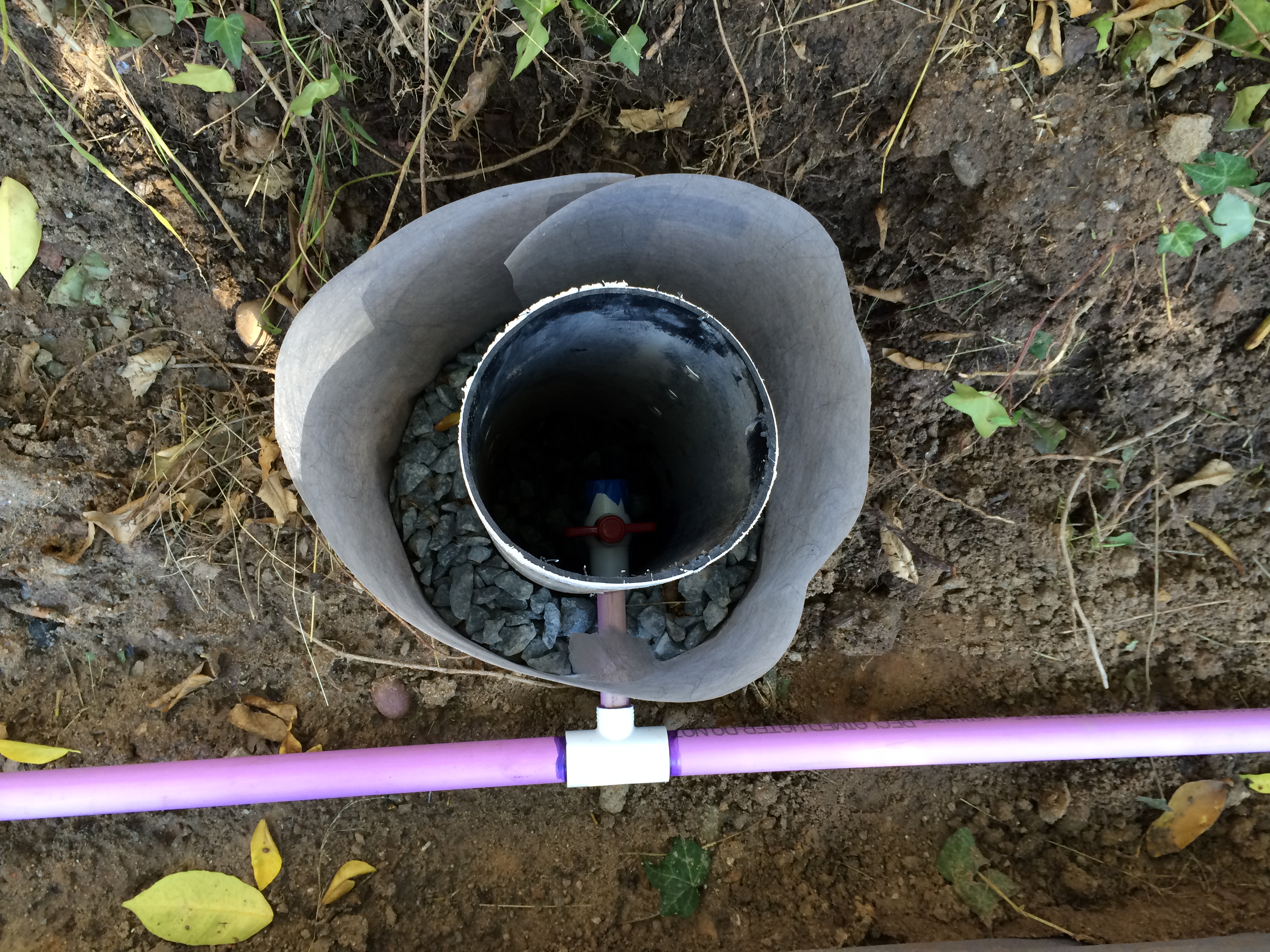
An example of a flush line. Yes, I know what it looks like. It will be covered with mulch, and after I took this picture, I decided to twist it around so it lies flat.
That detail out of the way, it’s time to install emitters. I knew that the spacing for me was 18″, so I made a little gauge out of leftover PVC pipe. Punching the emitters into the dripline is made MUCH easier with a special tool, that the manufacturer provides (for a reasonable price). If you’re punching in 250+ emitters into this dripline, then you REALLY need this tool! Yet, even using this tool, the emitters can be a bit recalcitrant. Usually you can feel the barb penetrate the tube and seat properly. If in doubt, give the emitter a tug to make sure it’s secure. Even so, you’ll probably have a few blow off when you first turn on the system. In most cases, reseating the blown-off emitter with the tool will solve the problem. If not, then you can install a “goof plug” and pop the emitter in someplace else. Make SURE you get some “goof plugs” so you have this option.

Anatomy of a diaphragm pressure regulated drip emitter.

Emitter installed in the insertion tool.

Punching in the emitter.

This is the hole that the barb in the emitter punches into the polyethylene dripper line. The material is elastic and deforms, which is good because it provides a good seal.
Emitter installed in the polyethylene dripper line. Note that there is a dimple in the line. This is apparently OK because they all look like this and don’t leak.
Now that all the emitters were in, it was time to run a test. I had previously hooked up all of the irrigation control valve wires to a temporary controller (because I don’t have my smart-home infrastructure built yet) and I now programmed it and turned everything on to make sure it was working. Sure enough, an emitter blew off, but I re-inserted it, and re-ran the test with no problems.
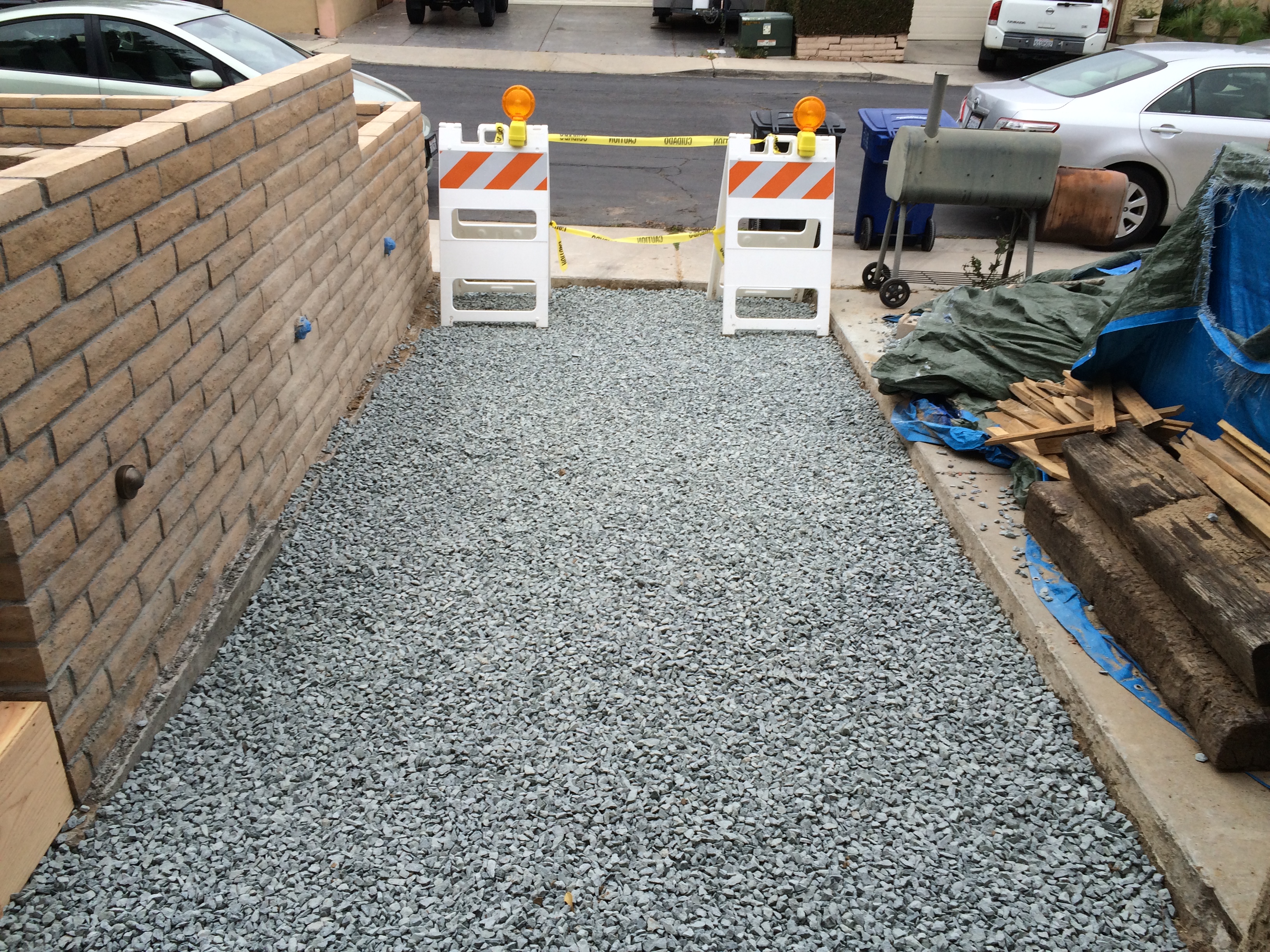
After the drip system is in, the next step is to mulch. I suppose you could plant first and then spread all of the mulch around the plants, but I figured it was easier to get the mulch in place first, and then push it aside where I wanted to put the plants. Probably about the same, amount of work overall, but because I was using bulk mulch (way cheaper), I wanted to barrow that around before I put up the gate and fencing around the front porch so I could more easily maneuver the wheelbarrow.
It was finally time to order the plants. We had a few in pots that we wanted to keep, but by and large, I needed to start from scratch. Shopping for plants can be quite intimidating because of the large variety available. The best thing to do is to figure out what constraints you have (size, sun, water) and then go with plants that tend to work well in your particular area. Even so, there are still a substantial array of choices. After much deliberation, visits to nurseries, and many hours online, I came up with a handful of plants that I thought would work well together. I put them in a list and sent the list to my favorite nursery, thinking that they would order it and deliver it. Well, that didn’t work out so well because (a) several plants weren’t in season, and (b) I didn’t get a chance to see them in person. What I ended up doing was visiting the nursery several times and having the folks help me make good choices of what they had in stock. If I had to do this over, I would perform the research as I did, but then take the list of plants and have the folks at the nursery make suggestions and recommendations based on the overall guidance of the original plan and forget about the delivery or special order stuff.
Fortunately, planting is a pretty straightforward process. (1) Position your plants. (2) Move away the mulch and dig a hole. (3) Toss in some fertilizer. (4) Set the plant in the hole and backfill. (5) Put the mulch back over the dirt. (6) Repeat for the other 49 plants you bought. It took me an afternoon to plant my herb garden and another afternoon to plant the rest.

Irrigation and mulching in place, I’m ready to plant!

Ready to plant the side yard. This shows how I arranged and spaced the plants while still in their containers. Much easier than digging a hole, planting, and finding out that it really wasn’t where you wanted it.

The center planter will be a succulent garden. All drought tolerant!
Finished edge plantings. Here you see ornamental ryegrass, salvia with red blossoms (substituted for bougainvillea), and creeping rosemary.

This is the herb garden. It doesn’t look like much now, but I have lots of yummy treats in store once this gets going. 4 kinds of mint, 2 kinds of thyme, 2 kinds of oregano, italian parsley, chives, culinary lavender, lemon verbena, lemon grass, and sage. I already have a mature culinary rosemary bush, and I have another plan for the basil garden (on the wall under the trellis).
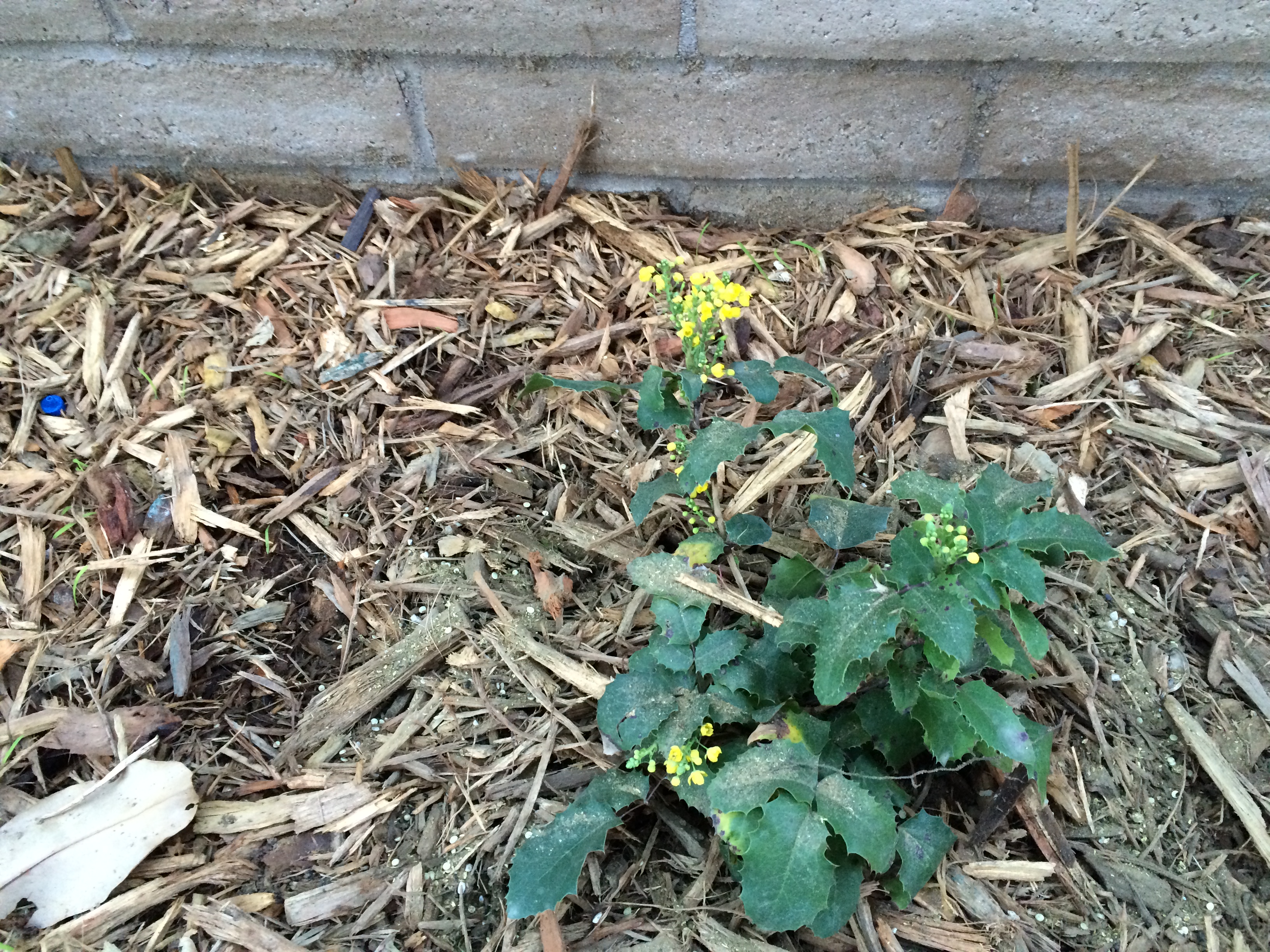
This is a shade-tolerant, water friendly plant which will grow into a nice evergreen bush with yellow flowers. I have no idea what it’s called. That’s why I go to a nursery and have the folks there give me suggestions.

My new mexican thornless lime tree on the left, and a poinsettia on the right. I got the poinsettia from a colleague at work who was selling them on behalf of his daughter. This was 2-3 years ago and the thing has survived, so it’s a hacker and therefore has a place in our garden. I hope that it grows to be the nice evergreen bush that poinsettias become, now that it will have proper care.
Now I have a nice garden started, and just in time for the El Niño rains (that are starting as I write this). My attention now turns to the inside where I will undertake a serious “spring cleaning”, so we can get rid of the stuff we really don’t need, and the rest has to be pushed around and/or go into storage so we can move out of our bedroom and garage, and start the work from the INSIDE. Yes, this project is only half-done and some of the worst is yet to come. But my wife has new-found confidence in my ability to design, build, and make things look nice. That outlook will now be tested. (Again!)