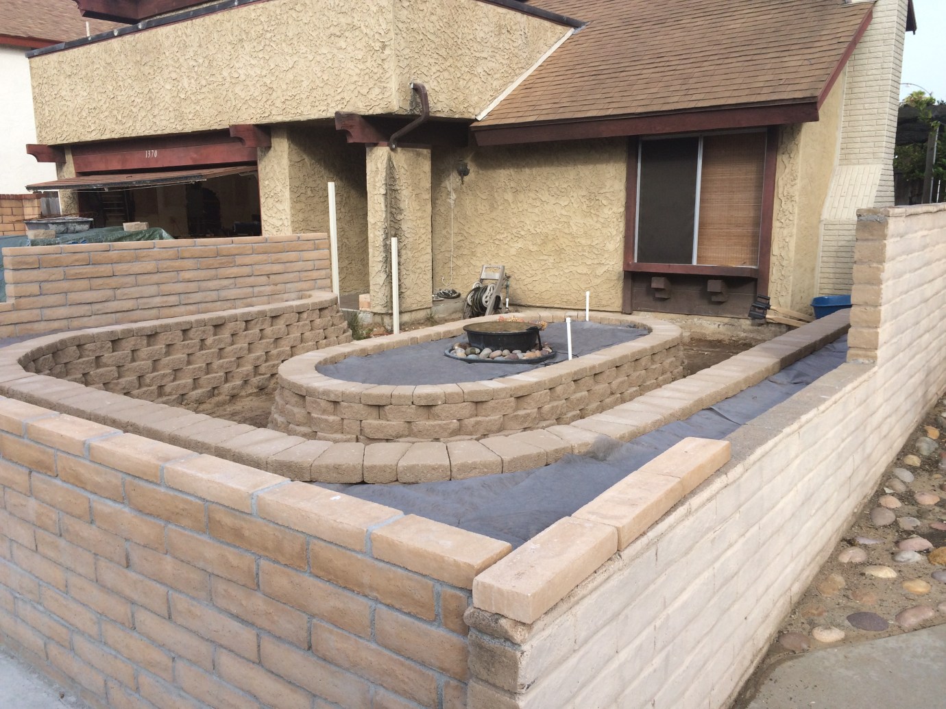
As I’ve mentioned before several times on this blog, all major projects will take some unexpected turns. I had a good head of steam going with finishing the front yard, but, in the back of my mind, I had one piece of unfinished business. When the inspector came by back in December to OK the burial of services, we discussed the ground for the electrical system. He suggested that I check what kind of grounding system I already had in place, and I might be able to use it with no further work on my part. Well, to do that, I had to remove the drywall from the back of the main electrical panel, and to do that, I had to take off all of my tools from my pegboard and unload my workbench. So, because that was a big job, I kept putting it off. But now that I was getting ready to pour concrete, I had to get this resolved. I surely did not want to have to bust up newly poured concrete!
The first step was to unload and dismantle my workbench. It was kind of a POS to begin with because I used cheap prefab cabinets made of fiberboard. Maybe OK for a rental unit, but the cardboard drawer bottoms really didn’t hold up to heavy loads like tools and boxes of metal fasteners. So it was destined, at some point, to go. But what to put in its place? I mean, any self-respecting DIY’er needs a workbench! All kidding aside, your workbench is an essential tool, if for no other reason to lay out your work and materials. So, now I had to build a workbench. I wanted to get this done quickly, but the more I thought about it, I did not want to just build a “throw-away” bench. Was there a design out there that was relatively quick and easy to build, but would be something that I could keep and use for years to come? The short answer was yes. In fact, there were plenty of them. The Internet is chock full of designs, but also, because I use a 3D modeling program called SketchUp, there is a tremendous online presence which has a bunch of pre-designed models just waiting to be used. Turns out that woodworkers use SketchUp a lot, so I was in luck.
I found a really nice design by Tom Caspar of the American Woodworker magazine. This was a very functional workbench, made of common lumber you could get from a big box store, and it had a number of features of a traditional master carpenter’s bench, including a large face vise, a tail vise with provisions for bench dogs, and a tool tray. I added a couple of shelves and some retractable casters, and voila! A functional, inexpensive, and easy to make workbench. OK, well inexpensive is relative. I probably spent about $500 on materials if you include the vise hardware and casters, but I see these “works-of-art” workbenches made of hardwoods and fancy hardware that sell for $2,000. I’ve also known other woodworkers that pay that much for just the raw materials (good hardwood is expensive). Actually, I don’t understand why there would ever be a market for a pre-made master woodworker’s bench. If you have the woodworking skills and interest to actually use a bench like this, well, you would just make it, right? I mean, isn’t that what woodworking is all about? Unless you’re just a pretender. Some things will always remain a mystery to me.
Easy to make is also relative. I have a pretty well-appointed woodworking shop with a table saw, drill press, jointer, planer, bandsaw, lathe, and dust collection system (ShopSmith). (I really like my ShopSmith and have used it ever since I bought it back in 1990 — I think it’s a great solution for a complete workshop in a small space.) I also have a sliding compound miter saw that is mounted to a workstand (that I built). I also have a special jig for my circular saw that guides it accurately when cutting sheet goods — just like a panel saw. So, with all of these tools, and a number of years of experience, I found it to be relatively easy, and I put it together in a couple of weekends. Here are some pictures,

Picture of the plans

Finished Workbench With Tools
and a link to the PDF set of plans: TOM’S TORSION BOX WORKBENCH REV 1.0
Finally, it was time to move all of the tools from the pegboard and empty the drawers. I was able to find some nice plastic storage tubs which fit very nicely on my shelves in my new workbench, so I was actually able to keep the garage fairly well-organized. I tore out and broke down the cabinets, pulled out the old shelving and pegboard, and prepared to demo the drywall. My first cut showed that there was no ground wire coming out of the bottom of the electrical panel. Not good. So I kept tearing down drywall until I found what looked like the grounding wire. It was a #4 aluminum wire (bad) that obviously was headed upstairs to the plumbing system (bad again). I was hoping to find a ground to the rebar of the foundation (also called a Ufer ground), but no luck. So, I had to go back to the codes to figure out my options. Here is what I found:

#4 Aluminum ground wire won’t be enough to handle a 200A circuit. Plus, it’s grounded to the plumbing system which is no longer allowed. So, I need a new grounding system.

An example of the crappy electrical installation in my home.

More code violations! If I can, I’m going to replace every wire in this house! Especially because they’re aluminum.
Turns out that I had already done a lot of research. I knew that there was a possibility of not finding a good grounding system and that I would have to install a new one, so I started looking into what that would take several months ago. A residential electrical system needs a good, low impedance connection to the earth for several reasons. (1) The earth ground will help protect your house and all of your electrical/electronic devices by dissipating high voltages that could occur due to a lightning strike or an electrical surge on the electric grid. (2) The earth ground serves as a zero voltage reference to help keep voltages constant at your appliances and receptacles, and serves to dissipate stray charges caused by static electricity build-up. (3) The ground allows a return path from your electric service panel to the electric utility’s supply transformer to correct imbalances in your electrical system. (WARNING — TECHNICAL STUFF AHEAD!)
Your electrical system connects to the electric utility through a “transformer” which is a relatively simple device that, through the magic of Maxwell’s equations, takes high voltage (typically 7,500V) from the electric transmission lines, and converts it to lower voltage (240V) suitable for residential use. This transformer splits this voltage into two legs using a center tap on the secondary windings of the transformer as a common return line. Hence your electric panel has two voltages available: 240v across the ends of the transformer, and 120v taken from one end of the transformer to the center tap. This center tap is called the “neutral” and, in theory, if all loads on both sides of the transformer are balanced, the neutral current is essentially zero. However, that’s rarely the case as the various circuits in your home draw from either one or the other side of the neutral (center tap) and some times they’re on and sometimes they’re not. So there is ALWAYS some current flowing through the neutral, and the grounding of the neutral to earth allows a return path for these “stray” currents to go back to opposite winding of the transformer via the ground on the transformer side.
Well at least I think I understand it.
Back to installing the ground. Because of the dry conditions, the best ground you can get in the southwest United States is a Ufer ground, or more appropriately called a “concrete encased electrode”. It turns out that the rebar in your slab and foundation makes a pretty good ground to the earth because concrete is conductive and the large surface area exposed to the earth provides a good, low impedance connection. But that didn’t do me any good because I’m not pouring a foundation. Another option is to use the water supply system provided that it is conductive. Even though the code allows it, this can be problematic because (a) somebody can always come in and install a non-conductive fitting (e.g., PVC) and (b) my water supply line is covered by a protective plastic sleeve to help prevent corrosion, which makes it useless as a ground. So the best option was for me to use grounding rods.
Grounding rods are 8′ copper encased steel rods that are driven into the ground. Normally they are driven straight in, but if you have rocks in the way, this can be problematic. So, if you run into rocks, you can drive the rods at a 45° angle, and if you STILL run into rocks, you can bury the rod horizontally at a 30″ depth. So, I decided to go with a rod grounding system that consists of two, 8′ rods driven at least 6′ apart (2x length, or 16′ is best) and connected with a continuous #4 solid copper wire. From the Internet I learned that the best way to drive these rods was to pony up the bucks to rent the largest hammer drill you could carry and rent a special rod driving bit to go with it. This YouTube video showed somebody driving the rod in about 40 seconds, but I really didn’t think I would be that lucky. Nevertheless, I procured the necessary materials and tools and merrily went to work.
The first attempt was about like I expected. Although I was hopeful at first, the rod stopped about half way in, so I had to do some digging and, through some imaginative extrication work involving a pipe wrench and swearing, get the damn thing back out. At least I learned how to climb up a stepladder cradling a 40# electric jack hammer and lifting it up to gingerly rest on the top of the rod and then balancing the whole affair and hammering it in without falling off the ladder and breaking my neck. With that bit of confidence under my belt, I relocated the rod and tried again. Same result. So now, I knew I had rocks about 4′ deep and the next step was to drive at a 45° angle. I extracted the rod using the same methods mentioned previously, except for double the swear words, and relocated the rod and tried again. This time it went in farther, but still stopped. So I decided to dig the 30″ trench and just bend the end in to fit. However as I started to dig, I found out that the trench was running into existing buried electric, phone, and cable services. So I had to stop and, once again, extract this stupid rod. It just looked like it was shaping up to be this kind of project with multiple problems and no real end in sight. Not that I’m inexperienced in this situation.
So, I did some more measurements and figured out where the rods should go so as not to interfere with existing services and maintain a minimum of 6′ spacing regardless of whether I had to bend the rods over or not. With low expectations, I tried to drive the rod for the 4th time and, by God, it went in. Like a hot knife through butter! Just like the video. So I was lucky, and being never one to turn down a lucky streak, I tried again with the second ground rod. It was going in pretty good until about the last 18″, and at that point I was loathe to give up the fight. So I put some serious ass into that jack hammer and the rod started to move slowly. I kept with it until my fillings were about ready to fall out, but hey, I got it all driven in. No need to trench or remove the rod and try again. I was all done!
Well at least the hard work was done. I had to unwind the copper wire, secure it to the rods with acorn nuts, and then put the wire in a little bit of PVC conduit so it would be protected from damage from where it exited the grade to where it went into the house. Here are some visuals:

Getting ready to drive my ground rods. I wanted to drive 3, but I ran out of wire because of where I had to locate the first 2 rods. Only 2 are required per code.

Ground rod driven at 45º with proper ground wire installed.

Grounding Electrode Conductor (GEC) must be one continuous wire. (Splices must be either welded or use approved specialty connectors.)
Now with the ground in place, I’m all set to finish shoveling and leveling the final grade and get some gravel in to get ready for the concrete pour. The inspector came in yesterday and took a look and said I was good to go! Now, onto the backfill and concrete pour! Good thing that I checked all of this out ahead of time!
