Let’s face it: I’m a dedicated cat lover. I didn’t used to be, but when I was first dating my yet to be wife, she had mentioned that she liked cats and had many a fond memory of them. My tiny little pea-brain thought: “Well, wouldn’t it be nice to get her a cat because she likes them so much.” She did like the cat, but it came with the newfound responsibility of being a “cat-daddy”. It was all good, though. She showed me how to relate to them, and that they were very affectionate, but their life was lived on their terms, and after a fashion, I came to respect that. Since then, we’ve had many a cat, and I now believe that those who don’t like cats, don’t know cats.
Cats have always come into our lives either through the local shelter, or have just shown up. We never pass up the opportunity to attract a stray and needy cat, and, if it is not obvious that the stray is neutered, we get it to the vet (trapping it with a live trap if necessary) and take care of that little piece of business. We started with the one cat way back when, but as Earnest Hemingway says: “One cat just leads to another.” so we’re at four (at the moment).
A couple of things that cats need are (a) territory they can claim and (b) places for their territory that are interesting to them where they can perch, play, sleep, and watch. For indoor cats, this can present a challenge, especially if you have more than one cat. The answer is to “catify” your house. There are lots of good ideas out on the Internet about “catification”, and these primarily emphasize making use of vertical spaces, such as shelving, steps, climbing posts, and perches that allow the cats to move around and find more space. However, all cats like to be outdoors. The conundrum is that outdoors can be dangerous to cats because they can become prey to other animals (like coyotes) and can become injured by other cats, cars, and mean people. But, what if you were able to put them in a big cage? And what if that cage shared a wall with your home so that they could have a private “kitty door” they could use at their whim? And what if you made that cage big enough for people to have a couple of nice outdoor chairs and a small table so you could enjoy the outdoors with the company of your cats? Say hello to the “catio”.
A catio is a patio that has been modified to accommodate the needs of cats that keeps them safe while they enjoy the pleasures of the outdoors. Some are very small — basically a shelf extending from a window with a cage around it. Very popular in cities. But for a home that already has a patio with a patio cover, as it is in my case, it is a simple matter to add some rudimentary framing, a couple of doors (one cat, one human), and some wire mesh, to have a nicely defined outdoor space that can be enjoyed by the whole family. Yes, cats are part of the family. But, to really bring it up to proper “cat standards”, one needs to add some cat specific architectural details that give the cats places to hide, peek, perch, watch, climb, run around, and sleep. These don’t necessarily have to be complicated, so I decided to have some fun in designing the interior of the catio to provide the cats interesting and fun things for them to do, while still maintaining a sense of style. Here are some pictures of the design.

Here is a rendering of the catio with the cat “toys”. There are numerous features that are attractive to cats, such as vertical interest, views outside, places to run, hide, and peek, and places to climb and scratch.
The actual building of the structure is pretty simple. I used basic 2x dimensional lumber for framing everything out, and decided to use deck screws to put everything together. Because none of this is load bearing, and was built against the existing framework of the patio cover roof and posts, I didn’t need a permit. Having said that, I did use my SketchUp modeling program to do a detailed design because (a) it helps me visualize the final product, (b) helps me figure out how I’m going to build it, (c) helps me with the material estimates. I put some effort into the door because it has to be sturdier than a typical screen door, and if you’re using dimensional lumber that is pressure treated, it probably won’t stay square because it is sold as green (wet) lumber and will warp when it dries. I found out this the hard way with my first attempt at a catio. This time around I used kiln dried 2×6 lumber for the door and joined it with mortise and tenons, held together with waterproof glue and dowels. Here are some pictures of the final design.

Catio Framing

Catio Toys

Detail views of the construction.
And of the construction.

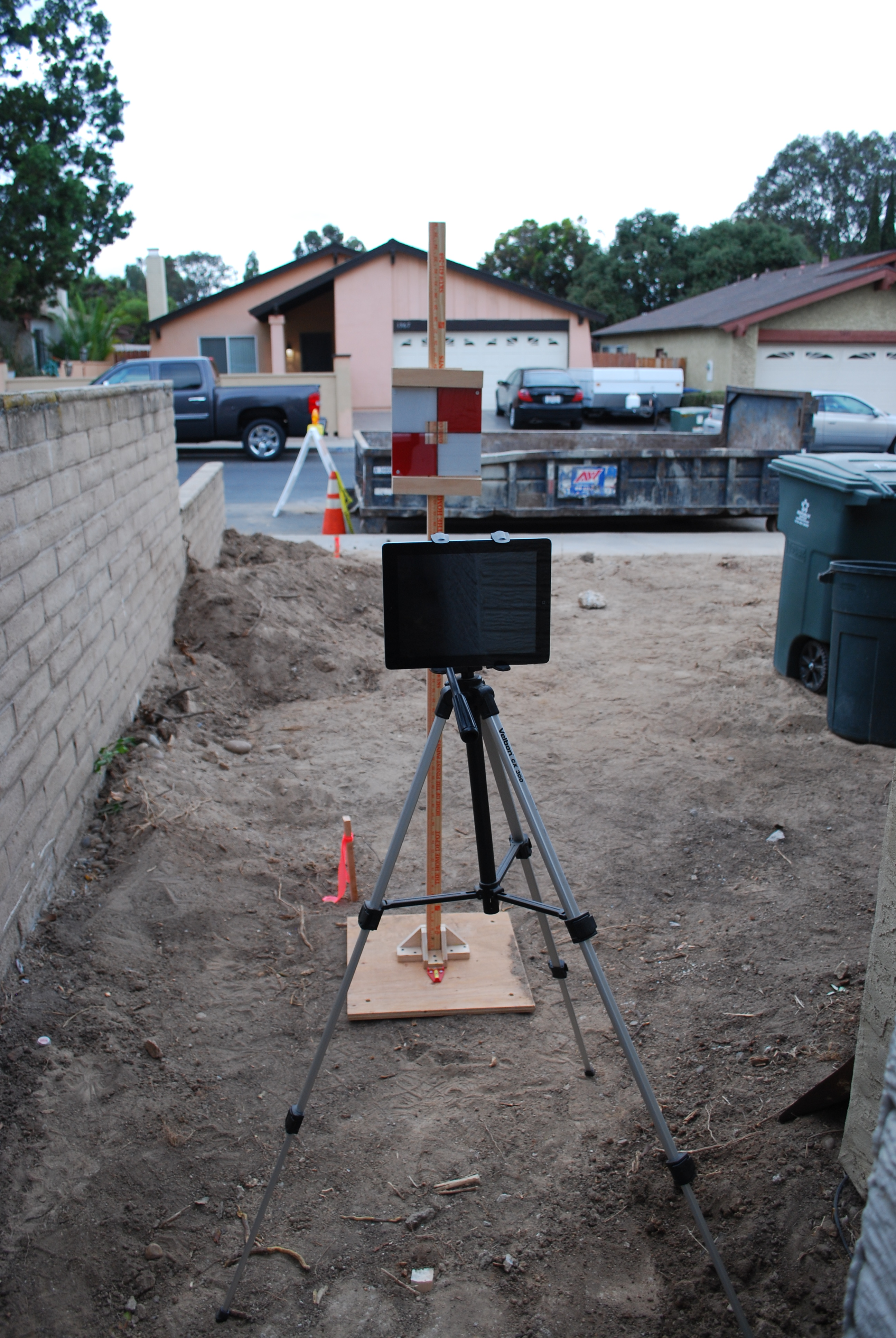
The “before” picture. All tools in place and materials staged (on the left). Time to start framing!

The framing is done! I paid particular attention to the frame for the door, making sure that it was square and plumb.

Framing is spaced at 36″ to fit the 36″ wide roll of wire mesh (with overlap). This minimizes the time cutting the mesh.
After the framing was up, I installed all of the “cat toys” and the door, and then took them all apart for painting. The plywood and untreated wood needs protection against the elements, and it’s easier to paint these parts while they are flat, and disassembled. They all go back together pretty fast!
The last part is covering the structure with wire mesh. I used a 1″x 1″ 14 ga galvanized mesh that is available from Home Depot if you special order it. The first time I bought this stuff several years ago, I paid about $100 in shipping because the stuff was not available locally. What I found out was that if you find the product you want from a manufacturer that does business with Home Depot, you go to their “pro” desk and ask them to special order it. No shipping charge!
I found the 1″ x 1″ mesh to be ideal because (a) it looks nice (chicken wire makes it look like a chicken coop — not my decor), (b) it’s sturdy enough so the cats can climb on it and not deform or make holes in it, and (c) it’s large enough to minimize the obstruction of the view from inside, yet small enough to prevent unwanted “visitors”. The visitors that are small enough to get through are taken care of by the cats….
I chose a 36″ mesh width because that fit very well with the proportions of the framing, which minimizes the amount of cutting of the mesh. It also makes it easier to handle when attaching to the framing.
Attaching the mesh single-handedly can be challenging because the mesh has a “memory” that tends to spring the damn stuff back on top of you and give you scratches. When people see my recent scratches, they ask if they are because of my cats. Well, in a sense, yes. But I digress. I found that laying a long piece of 2x lumber lengthwise will (a) prevent the roll from coming back on you when you’re cutting it, and (b) can help you stabilize the piece when you fit it to the frame. The other “must-have” is a pneumatic stapling gun. It makes aligning the mesh fairly straightforward, and for quick work in stapling it down the rest of the way. Yet another reason to buy that “new tool”. At least one new tool per project…. that’s my motto.

Using a spare 2×4 to hold the roll of wire mesh in place for measuring and cutting.

The mesh has a “memory” which tends to roll it back to its original shape. If you try to straighten it out, chances are it will be deformed when you staple it in place. The best strategy is to work with the spring-back. Align to the framing by tacking the middle of one end to the framing, and then aligning one edge to the framing and tacking the edge in place. Once aligned, it is relatively easy to “unroll” the mesh as you progressively staple it to the frame.
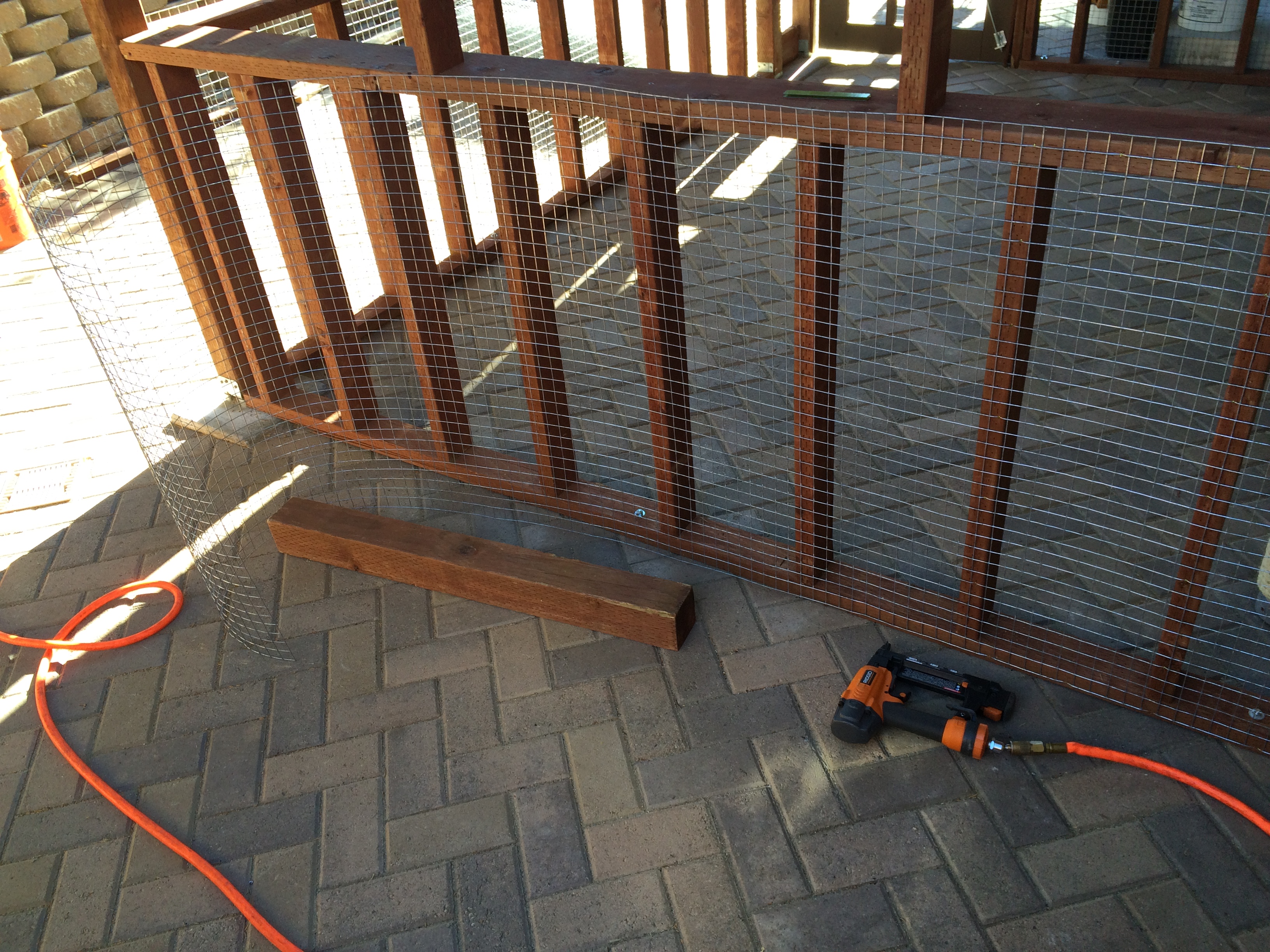
The 4×4 is being used to hold back the “spring” in the mesh. Once the mesh is aligned, it is easy to tack in place with the pneumatic staple gun.
Finally, having a little “cat door” is essential because you want the cats to enjoy the space when they want to. And you don’t want them bugging you. There are many kinds of animal doors available, and I chose one that had a magnetic strip which keeps the door vertical when not in use, plus a 4-way lock (open, locked both ways, locked in, locked out). Some come with an RFID chip that you put on your cat and the door allows only your cat to go in and out, but that was way too fussy for me.

The catio makes an elegant (well, at least consonant) outdoor space where we can enjoy our cats and the outdoors together. Is it cocktail hour?
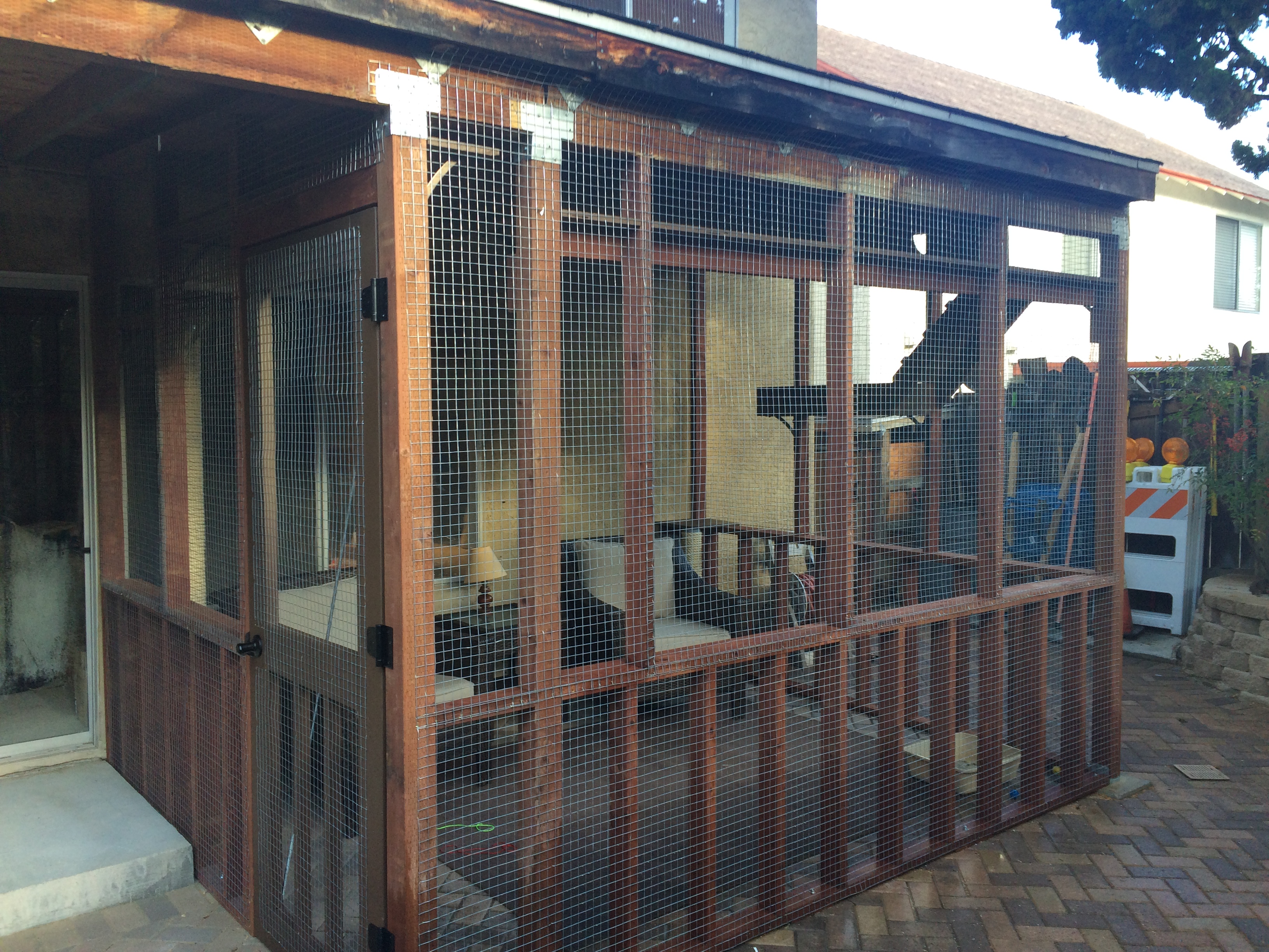
The finished product. Suitable for human and beast.

The catio should be appealing to both cats and their caretakers.
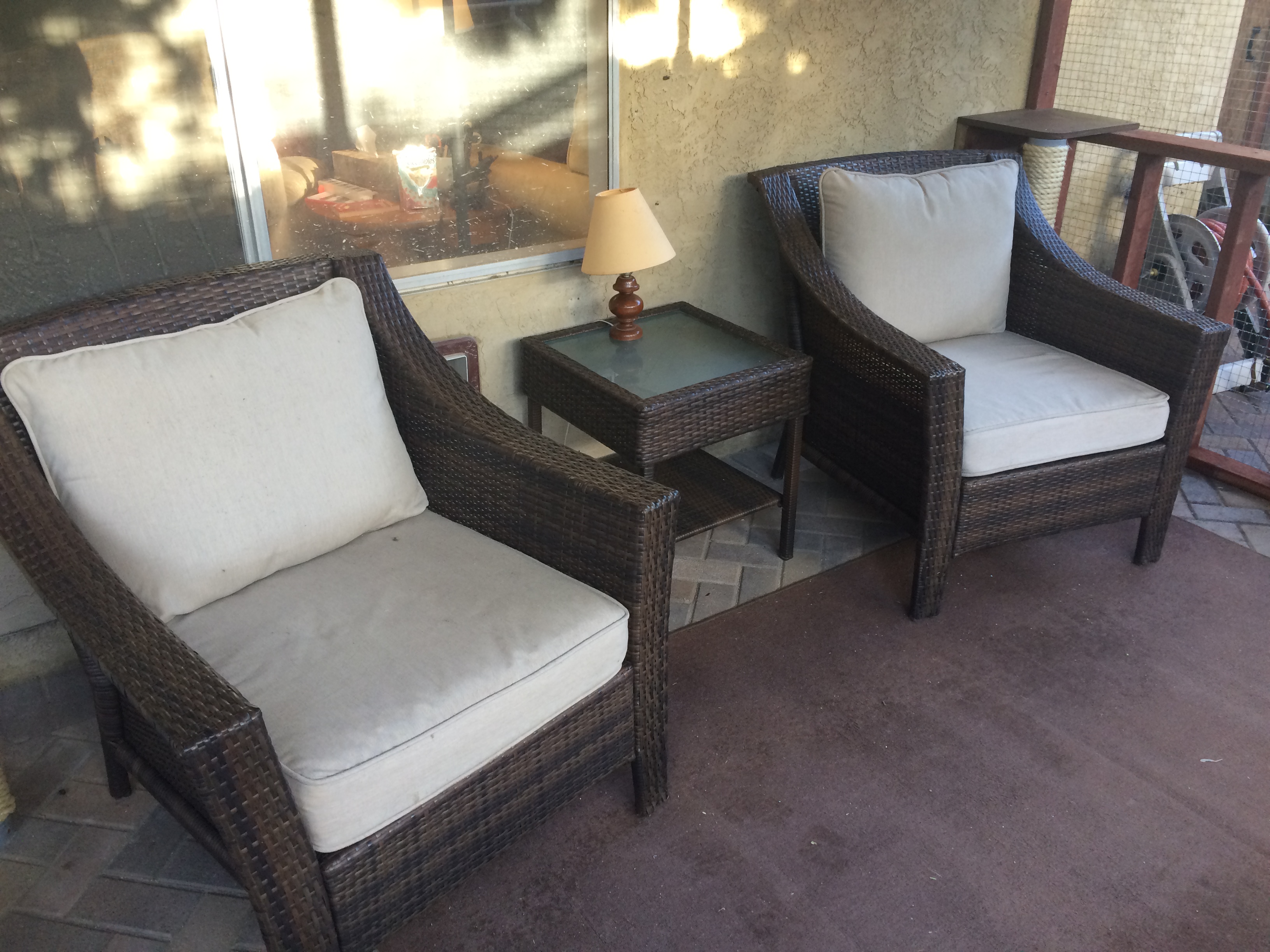
A catio should be a place where the cat caretakers can enjoy the space along with the cats. Cats like human companionship, and we can share and enjoy this space with each other.
Here is a video of our cat family: