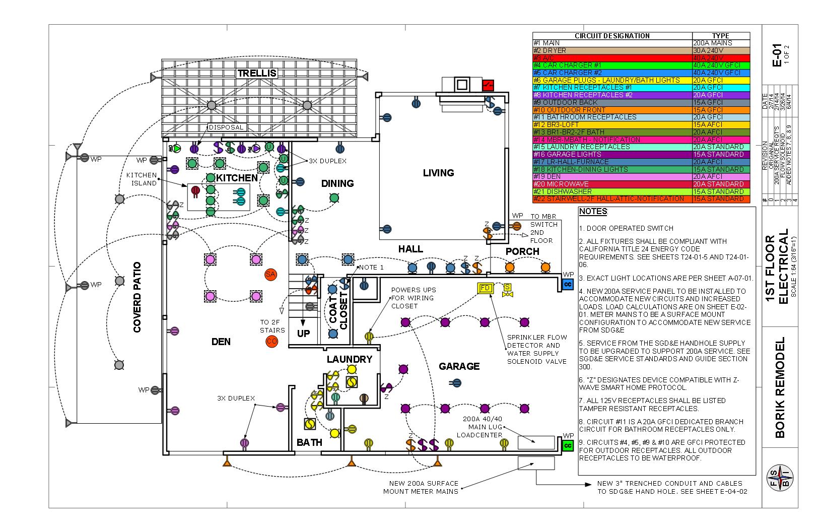
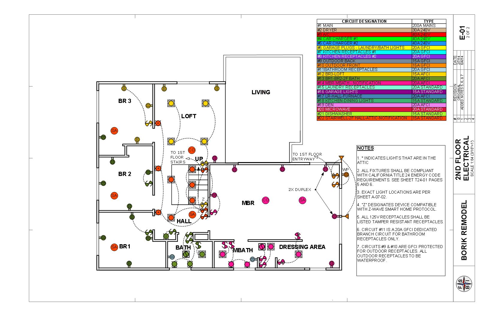
While waiting for some more vacation time to accrue so that I could take a couple of weeks off and do the master bedroom buildout, I had a few weeks with nothing planned in particular. So last week, I decided to get some of my electrical work in. I’ve been researching this for some time and came to the conclusion that I would get the new service entrance panel and breaker panel all mounted and connected, and then I could call the city inspector. After passing that inspection, I could then contact the electric company (SDG&E) at my convenience and have the upgraded services connected at a time convenient for me. So I figured I could at least get the panel installation done.
The first thing was to order all of the parts. I had figured out most of this during the design phase of the remodel, so all I had to do was to re-familiarize myself with the work I already had completed, and then go back into the manufacturer’s catalog (I chose Eaton), get the part numbers, and then type them into the Home Depot website and put them on order for home delivery (that was free). 3 days and $1,000.00 later, I had all of my panels and breakers at the ready.
The next step was to open up the panels to see exactly how they were laid out so I could figure out what would go where, what knockouts I would use, what types of conduit and fittings I would need and what kind of wiring to get. I didn’t need a lot of wire because the panels are back-to-back, but it needed to be pretty hefty wire because it carries all of the house loads. One thing I had to figure out was how to lay out the grounding bus and neutral bus. If this means nothing to you, then you can (a) read my previous blog entry on grounding, (b) go to this website (http://www.wireyourownhouse.com) which does a pretty good job of explaining the terminology, or (c) skip ahead and forget the technical stuff. Since I like the technical stuff and it’s my blog, then I’m going to tell you all about it.

My brand-new meter panel. This is just like Christmas!
In most panels, the service (main) breaker and all of the feeder breakers are in the same enclosure. This arrangement allows you to install grounds and neutrals on the same bus. However, once you have a panel which is fed from another breaker (called a sub-panel), you now have to electrically separate the ground from the neutral. The reason for this is because if you have a unbalanced load running, such as a single 120v appliance, then there will be current running on the neutral, and if that neutral is grounded, it will be running through the grounding wire as well, which can be dangerous. It also can screw up the operation of your Ground Fault Circuit Interruption (GFCI) and Arc Fault Interruption (AFCI) breakers.
So, the way I have my panel wired up, with the main service breaker as part of the meter panel, I have to wire the panel with all of the circuit breakers as a sub-panel. Yes, it’s a little more complicated, but I wanted to be able to COMPLETELY de-energize the circuit breaker panel so I could work on it safely. All in one panels are NOT de-energized because you still have live voltage at the cables coming in from the meter into the top of your mains.
No big deal. All of these panels come with a neutral bus that can be separated by removing a jumper bar, and you can now have a separate neutral and ground bus. BUT, I had one problem. Nowadays almost EVERY breaker is going to have GFCI or AFCI protection. Out of the 21 circuits in my design, only 3 use conventional breakers. The GFCI and AFCI breakers have a “pigtail” which forms part of the sensing circuit and connects to the neutral bus. But I really couldn’t see trying to wire the panel with just one neutral bus without having pigtails on the opposite side making a complete mess and a wiring nightmare. If there is anything that I know about electrical work, it is that neatness counts. Big time. Yeah, you can get it to work if your wiring is a rat’s nest. but it will be difficult to work with later, especially if you have to troubleshoot or add a new circuit. What I really needed was a neutral bus and grounding bus on each side of the panel so that I could have some flexibility in routing the wires.
Well, it turns out that the panel manufacturers make individual grounding busses that you can screw into holes in the panel that just so happen to match. So, I left the jumper between the existing ground and neutral busses and just didn’t connect them to ground, making them both neutral busses, and then installed two of the add-on grounding busses above and connected it all up with proper grounding wire.
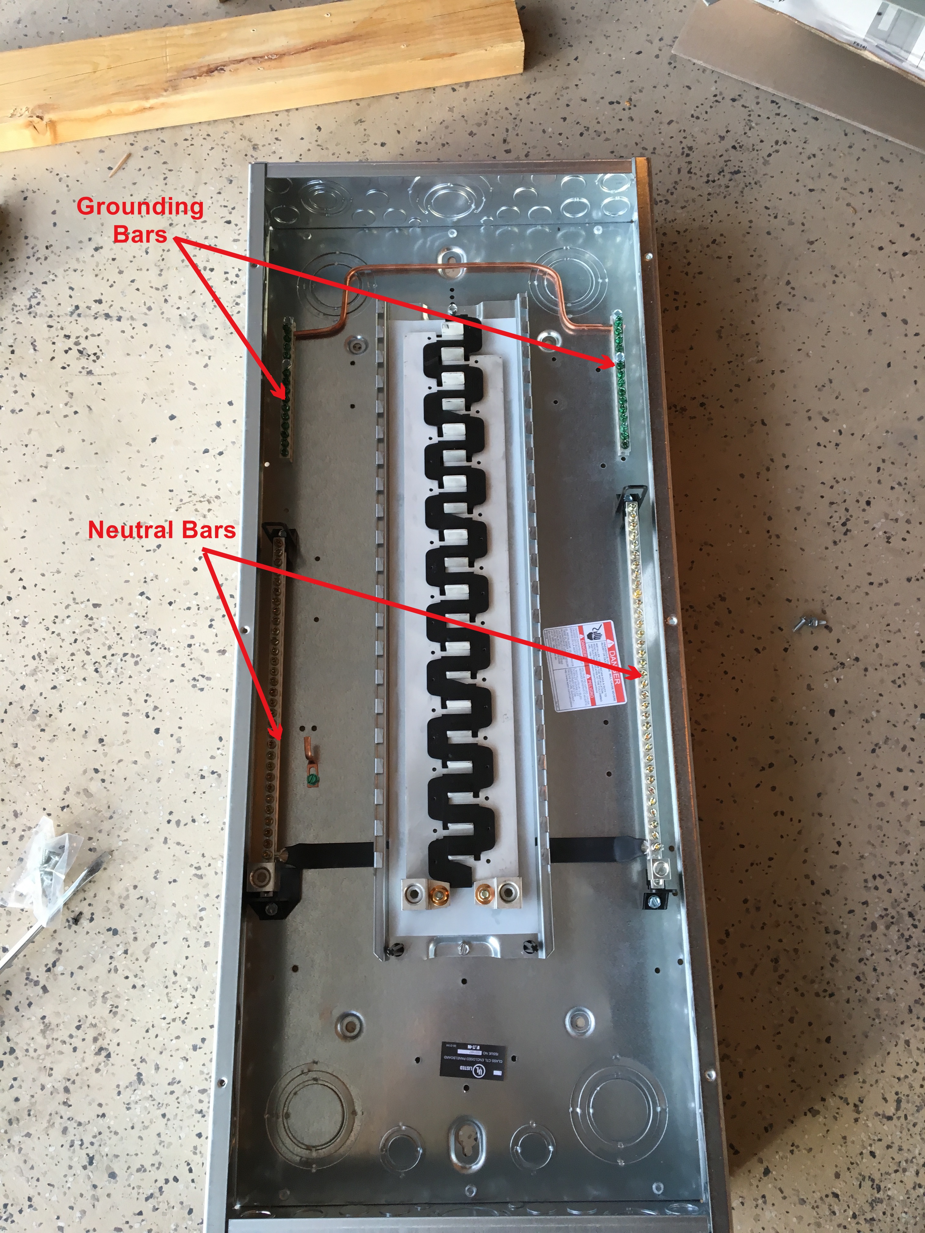
Indoor distribution panel modified for neutral and grounding bars on each side.
With that problem solved, it was time to locate the panels and figure out how to attach them to the wall. I also had to make sure that it was vertically located to make it easy to work inside the panels, and met the utility company specifications for the height of the meter. The last part was to figure out how the wires would be routed so I could identify the correct “knockouts” to, well, knock out.
After some preliminary fitting, I temporarily attached the indoor breaker panel between the studs and marked the hole for the wires coming in from the meter. I then removed the panel, drilled the hole with a hole saw, and installed a short piece of threaded pipe, or conduit in electrician’s terms, so that the wires would be protected as they passed through the wall.

Closeup of the through-wall conduit, which is the silver pipe on the lower right. The yellow water seal is visible.
Turning my attention to the meter panel outside, now could locate it using the conduit coming from the inside as an anchor point. After some trial-and-error and trimming of the conduit coming up from the ground for the main power lines and ground wire, I marked the location of the mounting holes in the back of the panel and drilled holes for the mounting bolts. I chose to use carriage bolts for mounting the panel because (a) they would provide a good anchor to the plywood of the wall and (b) they could protrude enough so that I could get a layer of stucco on the plywood before I mounted the panel. More on that later.

Exterior studs and conduit aligned for the outer meter panel. Yes, the stud on the lower left looks a little out of line, but I needed to “adjust” it to make it fit.
Lastly, I needed to fit everything together to make sure it all worked. So, out with the inside panel (again) to install the bolts for the outside panel, replace the inside panel and fit the conduit into the hole in the wall, fiddle around with the outside meter panel to align it with the main power, ground, and thru-wall conduits, and finally fit the panel onto the mounting bolts. How does it look? Ugh! The damned thing was leaning over! But, never a project without some kind of do-over, and because I do a lot of this do-over stuff, I’m pretty good at it. One hour later, voilá! Nicely done.

Outside meter panel temporarily mounted., Want to make sure everything lines up before putting on the waterproofing building paper and stucco.
Well, maybe that wasn’t the last step. I needed to make sure that the wall behind the outside panel was properly waterproofed, and if I installed it directly to the plywood, that would be impossible. The correct solution is courtesy of my favorite stucco guy, Kirk Giordano (http://www.youtube.com/user/StuccoPlastering). He showed a video of putting up stucco behind a new electrical panel with all of the proper waterproofing. In his instance, the panel was already located, but In my case, I could remove the panel to get better access. The key is to properly waterproof plywood with 2 layers of building paper, making sure that you flash and counter-flash around the conduit through the wall and the mounting bolts. Then, it’s time to do some stucco work! I really didn’t want to do a whole lot of it — just enough to make a nice surface in back of the panel. The professional stucco people that I plan on hiring will feather in around the panel and it will all look nice in the end. My job was just to make sure that I left enough room for them to tie into the paper and the lath when they come in to do the finish work.

The studs and conduit are properly wrapped in masking tape to shield them from the onslaught of stucco mud.

Meter panel mounted in the final position. I tried to make the wall in back waterproof, yet easy for the stucco contractor to come in and finish around the panel.

Closeup of the sealer locknut. This is a great installation.
Now the fun part — wiring! To me, this is a fairly straightforward task that is not particularly physically taxing, and you aren’t under any time pressure, like you are with masonry, and it’s pretty clean work (no mortar, sawdust, paint drips, water, etc.). My primary objective when doing wiring, other than meeting all specifications (e.g., wire sizes, connectors, strain reliefs, grounding) is NEATNESS. Especially in the main electrical panel. Wires should not just cris-cross all over the place, but be neatly run, vertically and horizontally, so it is possible to easily follow where each wire goes. As with all projects, a little forethought can go a long way, and in this instance, I figured out that I needed to route the ground wires first because I had to snake the wire coming in from the meter panel in back of the neutral bus on the breaker panel. I then had to connect just 3 more wires: two hot and one neutral. But these were BIG wires. Well, cables if you want to be more descriptive. For a 200 amp service, 2/0 copper is sufficient. There are some techniques for handling this size of cable, and I learned a lot from the Internet, as well as a great book by Rex Cauldwell called Wiring a House (Taunton Press, 2014). But basically, all you need is a utility knife, a pair of linesman pliers, a hacksaw and a crescent wrench (you use the hole in the handle for bending the cable).
Here are some pictures that show some of the electrical details.

Elements of a meter panel. Cables from the transformer at the street come up through the big conduit on the bottom. The two power lines hook up to the bottom of the meter, and the neutral cable hooks up to the neutral bar. The meter goes into the base on the left hand side, The two cables coming out of the top of the meter base go to the main panel breaker. Cables for power and neutral will come down and feed back into the house through the metal conduit on the right. Everything on the left hand side is the responsibility of the utility. Everything on the right hand side is all mine!

Everything all wired up for action! The feeder breakers are installed back-to-back along the center so they make contact with one (for120v) or both (for 240v) of the hot legs. Outgoing wires for the branch circuits are routed in along the “gutters” adjacent to the hot legs. What is it about the trades and their terminology? Male and female fittings, nipples, studs, hot legs? Sheesh!
And here is a video of me putting all of this together.
All done. Now it’s time for inspection!