Roughing It

Now that the wall framing was up, it was time to start installing everything that goes inside the framing. That means electrical and plumbing lines, and in my case, data cables and fire sprinkler piping. In this entry, I’ll briefly address the rough electrical, plumbing, and data lines, as I will have a separate entry on the sprinkler system (because it’s unique and cool).

Rough service work begins with locating where you want to put stuff. For plumbing, that’s usually spelled out in the plans, e.g., where you want the sink, shower, and toilet, so that part is pretty easy, and the relevant dimensions of where the plumbing fixtures connect are standardized. However, there are some nuances that must be considered, and since I’m doing an entirely custom installation, I decided to get all of my fixtures up front. That way (a) I could look at the installation instructions and actually do measurements if I needed to, and (b) the fixtures all matched. It cost  quite a bit up front, but at least that expense is taken care of (!). So, I went ahead and marked where I wanted the toilet, sink, and shower drains and water supplies to go. Now, I had to learn plumbing.

Supplies 1

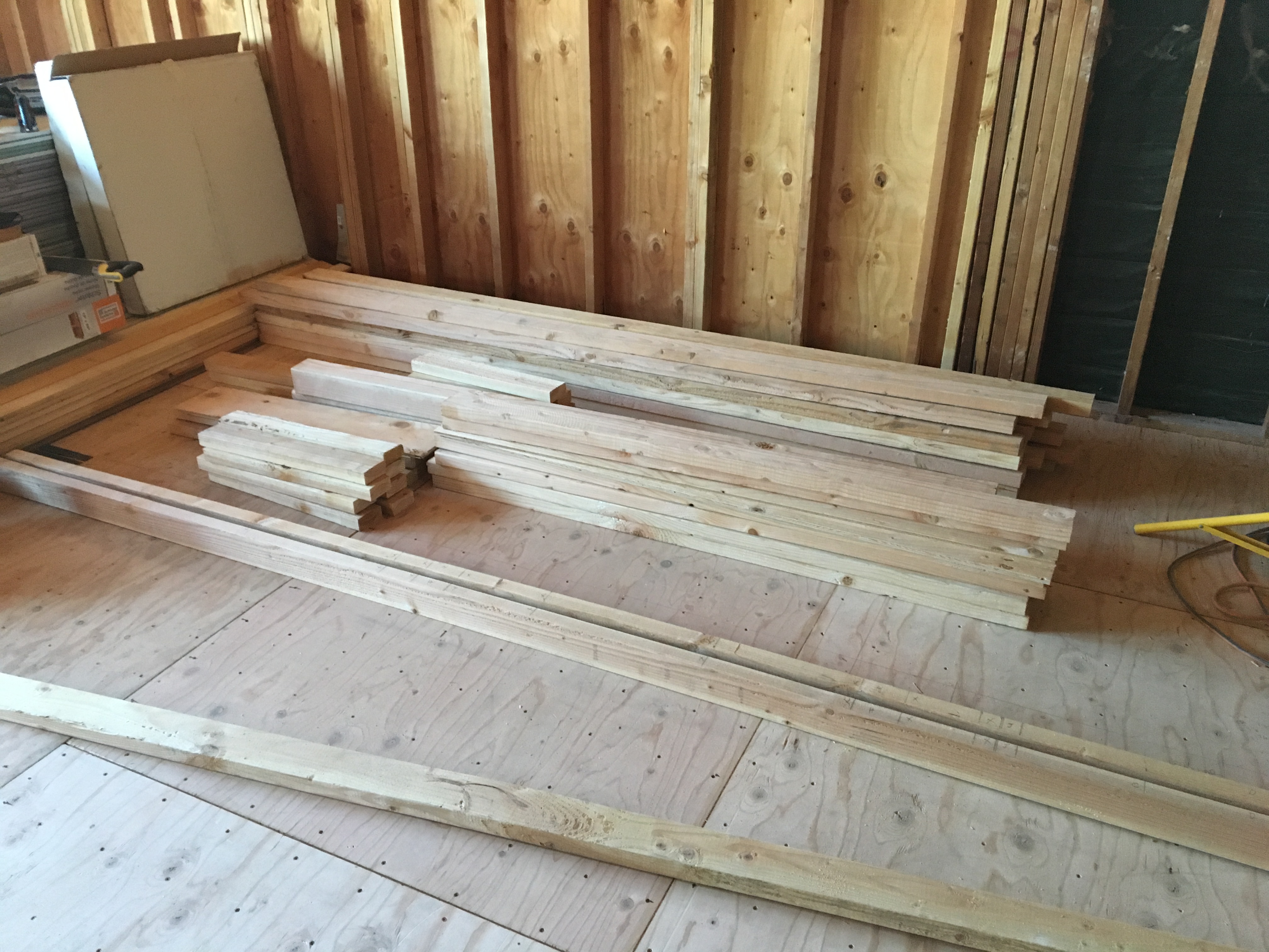
All fixtures and parts for the bathrooms, plus the toilet and sink for the MBR bathroom.

Supplies 2

The rest of the parts for the bathrooms. I also bought all of the tile at once to make sure I had it from the same run. Lots of stuff to warehouse!

As a chemical engineer and as an engineer on a nuclear sub, I figured I could deal with the technical aspects of a residential plumbing job. I had to review the relevant codes to make sure I was in compliance, but then I figured, how hard can this be? I was about to find out….

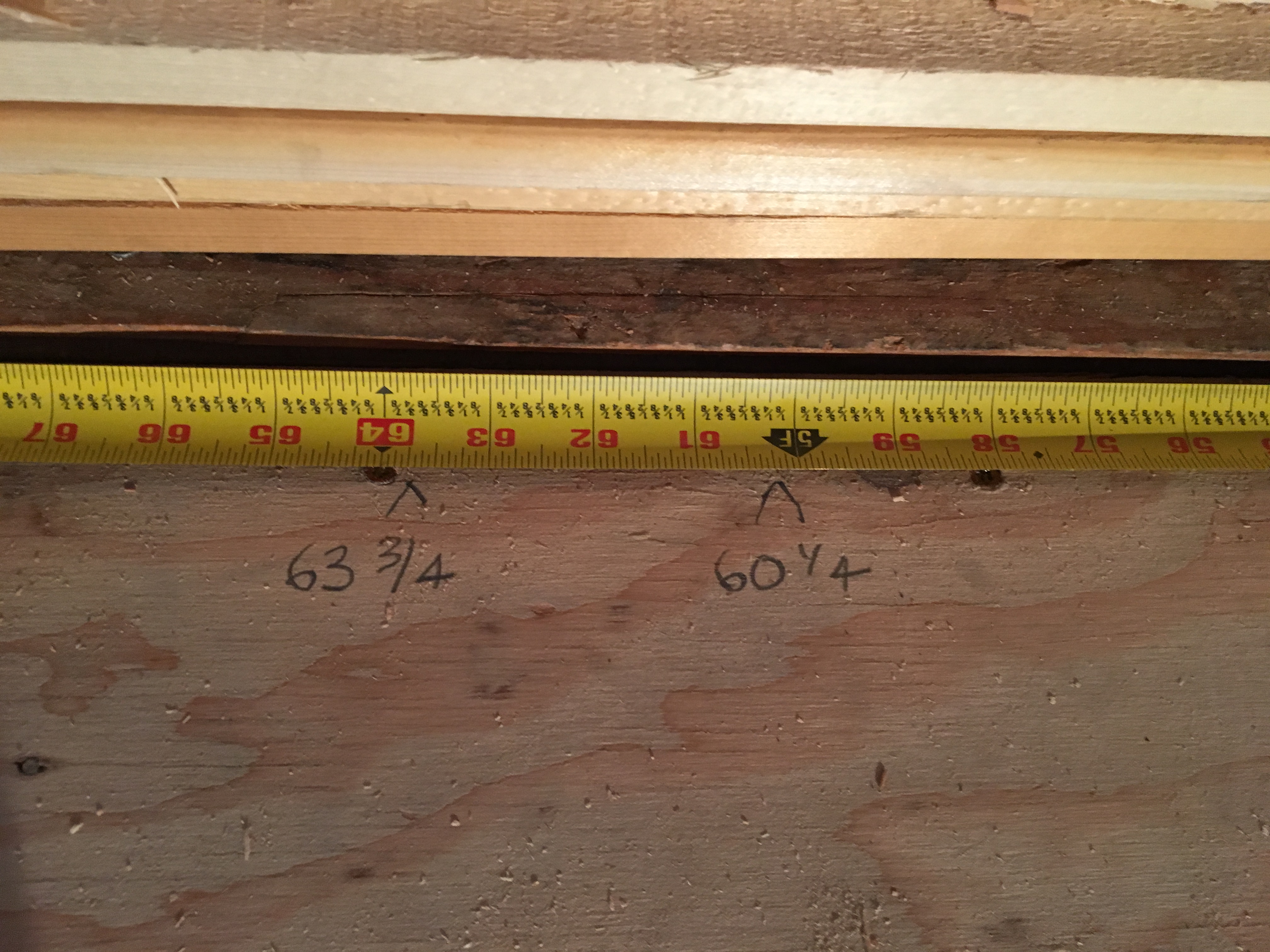
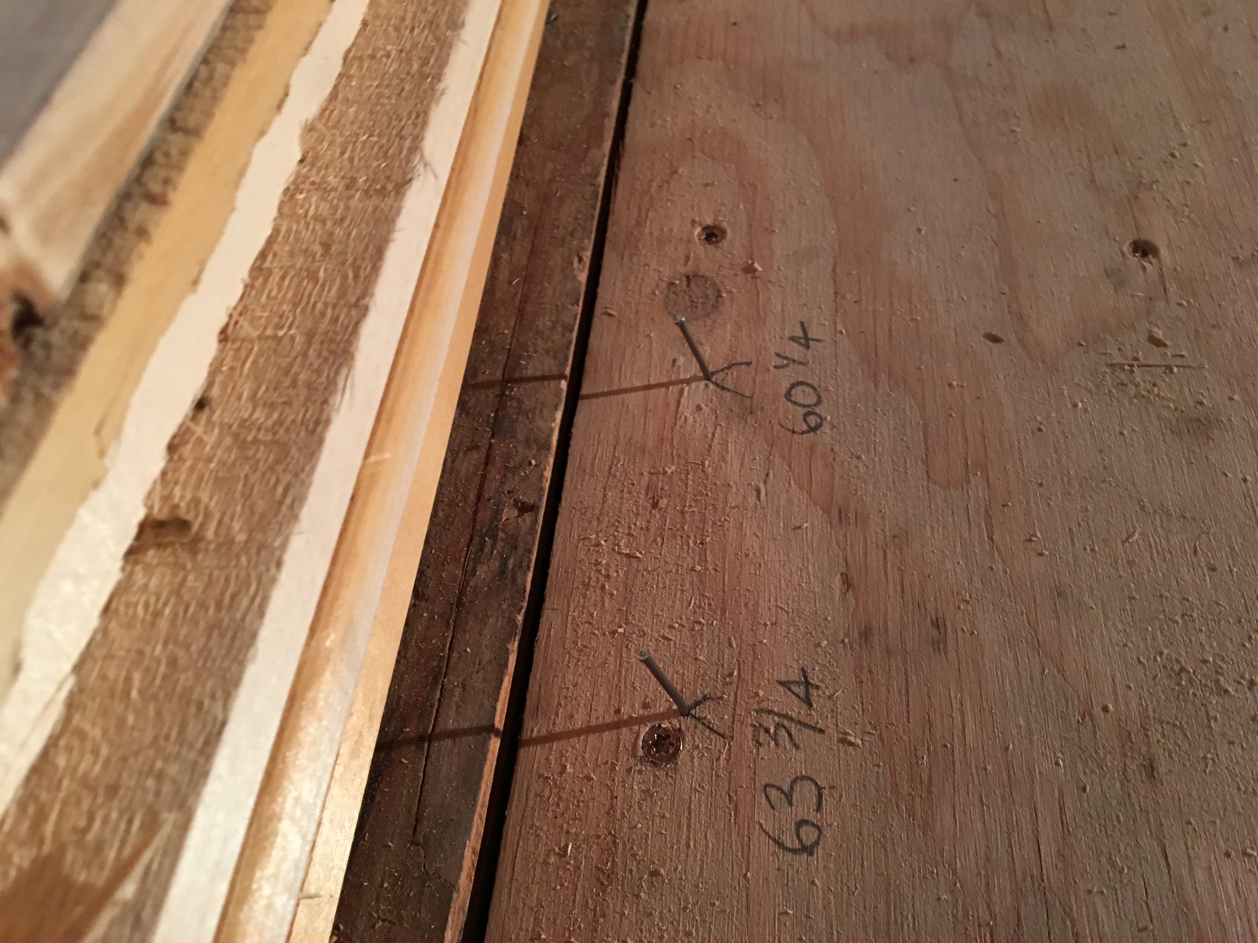
I decided to start with the toilet drain because it was the largest pipe and I found out I would have to be doing some tricky routing through the joists, which I had previously tripled to shore up the master bedroom floor structure. These extra thick joists turned out be be troublesome because the pipe had to be angled to get the slope correct and the hole saw that I was using was only slightly larger than the OD of the pipe. I eventually hammered it in but getting that last joint together was a bitch! I hope it doesn’t leak.

Toilet Drain

Toilet drain piping. See the tripled joists surrounding the pipe? I had to drill big holes through those and ram the piping in!

The next challenge was putting together the water supply system for the showers. I decided to ramp up the quality of the showers by installing a “smart” shower system that uses an electronic control in the shower to remotely control the mixing valve. I went with copper pipe because that’s what the house had to begin with, and I sure got some good experience in sweating the pipes together (turns out that it’s not that hard). The best advice that I got was to use MAPP gas instead of propane. The higher temperature of the flame makes the solder flow much better. Nevertheless, It’s a complex setup and I ended up gouging one of the press-fit O-rings when I inserted the pipe into the mixing valve, so it caused a bit of a mess when I turned on the water to pressure test.

Shower Mixing Valves Annotated

Diagram of the remote shower mixing valves. These are located in the garage directly below the bathrooms. The hot and cold water supplies connect to the mixing valves and the remote controller sets the temperature and volume through the controller signal lines. The water then goes directly to the shower head(s).

Remote Shower Control

Remote shower controller. This is all electronic and has a memory for 4 different settings (his/hers/morning/after workout/whatever).


I also found some cool water supply valves that were recessed into the wall and had a very clean look. They are called “stop pull boxes” and are made by a company called “LSP”. If you’re interested, here is their website: LSP Pull Stop Box

And some pictures:

Recessed Water Supply Valve 1

Recessed water supply valve. The valve is the brass fitting in the middle. If you look closely, you can see the ball valve itself (the silver thing in the middle). This is really slick because it’s behind the drywall and the valve is operated by a pushrod attached to the threaded rod on the left-hand side. Looks very clean after installation which I thought was important for a pedestal sink.

Recessed Water Supply 2

Recessed valve installed. The eustachon will cover the hole OK. The brand is “LSP” and the device is called a “pull stop box”.

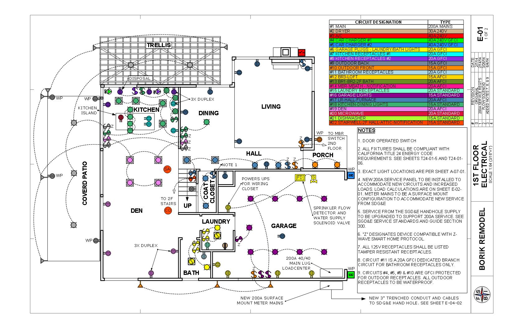
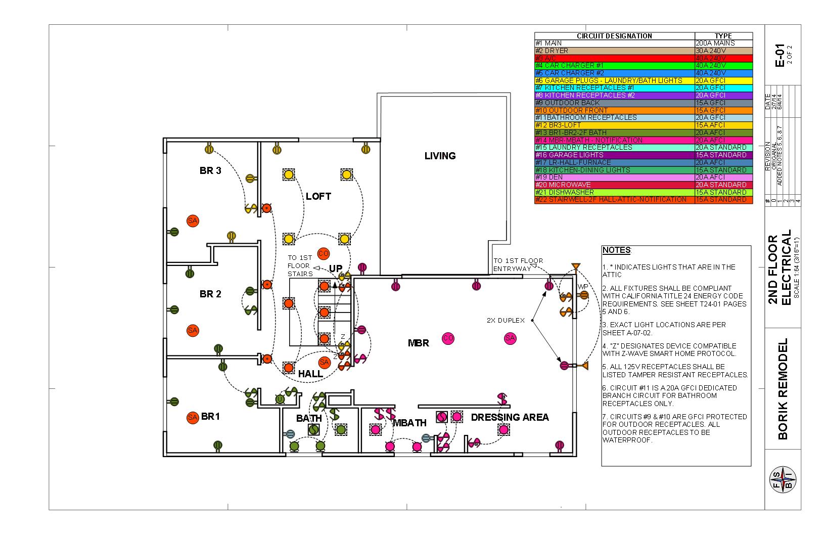
Going on to rough in the electrical, the plans are important, but I decided I wanted to do some Human Factor Engineering to get the exact location of the switches and lighting fixtures. I imagined myself doing everyday tasks like going to the bathroom, going to the shower, getting dressed, getting ready for bed, etc., and that helped me locate switches so that (a) they would be easy and intuitive to reach for and (b) I could operate the lights from different locations to minimize going back and forth when I wanted to turn something on or off. I also put in extra wall receptacle boxes, especially near where the bed and home office would be. Receptacle and switch boxes are pretty easy to install, so with that done, I was ready to start running wires.

Rough Electrical Bedroom

Example of the customization that one can do if you’re doing this yourself. I added the data and power boxes for the flat screen TV at the last minute (at no cost to the customer).

Running the wires for the rough electrical is something that’s not typically in the plans, which only show the locations of the receptacles, switches, and fixtures. I guess I could have done a schematic diagram, but I figured I would only be doing this once, and as long as I was disciplined in labeling each wire, I would be OK. To run the wires, I did have to plan out where I would be bringing in power from the electrical panel, and then how that power would be distributed throughout the room. The bedroom has two circuits: one for the sink in the bathroom, which needs to be a dedicated GFCI circuit per code, and one for the receptacles and lights. The “current” electrical codes (pardon the pun) require that receptacles in living spaces (bedrooms, living rooms, dens, dining rooms) be AFCI protected, so I needed to take that into account as well. The dedicated GFCI circuit was pretty easy (one wire from the panel to the receptacle), but the other wiring was more involved. The first thing that I did was to bring in power to a receptacle box, and then distribute power to the other receptacle boxes from there. The lighting circuits then tapped off the receptacle boxes.

One thing to keep in mind is the number of wires you have running in and out of each box, and the number of “devices” (switches, receptacles, both of which are referred to as “yolks” in the trade). There is a limit based on the heat load, and there’s a fancy calculation in the NEC, which it turns out, is not trivial. Here is a link to an good explanation. To make things a little easier, I just always get the biggest box possible for the number of devices I want (switches/receptacles) and have not run into any problems.

Electrical Switches and Receptacles

Good example of tailoring the electrical controls beyond the minimum. I can control both lights outside the garage (front and side) and the garage work lights from this location. The front garage door light can also be controlled from the master bedroom and the front door because it is a security and safety feature. I’ve also installed smart switches, where necessary, to allow control automatically under given conditions (e.g., coming home at night, opening the garage door, fire alarm or smoke detector goes off to illuminate egress routes). The receptacles with built-in USB chargers are a must, pretty much in every room.

Routing the wire takes a little planning. The main idea is to drill as few holes as possible, which typically results in running the wires in the ceiling. The other “trick” is to unroll the wire so that it’s flat. If you just pull the wire from the roll, then it will come out twisted and be difficult to staple neatly to the framing. Unrolling it before you pull the wire takes some effort: you have to pick up this heavy roll and heave it ’round several times. But it pays off with a neat and professional installation.

After the wiring was installed, I needed to energize some circuits so we could continue to live normally (if you call living in a house during a remodel “normal” — I guess it’s the “new normal” for us). Despite my supreme confidence in my ability to install some relatively simple electrical work, I flipped on one of the breakers and there was a loud “pop” (“arcing and sparking” in the trade).

Electrical Boo Boo 2

I thought I smelled something funny. Better find out what happened here!

Turns out that I tightened down the cable clamp too tightly and the clamp cut through the insulation and caused a short.

Electrical Boo Boo 1

Forensic analysis showed that I had tightened down the strain relief so much that it cut through the insulation and caused a short. More is not necessarily better!

I felt pretty bad and embarrassed about that, but later, after doing some additional reading in my electrical “how to” books, I found that these sort of things occasionally happen even for the pros. I guess that’s one way to get experience! At any rate, I had to pull the entire cable and replace it because you’re not allowed to splice or patch an electrical cable. All interconnections must be in electrical boxes that have an opening through the drywall to prevent an electrical short from causing a fire behind the drywall.

Lastly is the data cabling. For my project, I’m running a minimum of 2 cat6e ethernet cables and one RG-6 cable per room, but the the master bedroom and home office, I ran quite a few more. I started with standard electrical boxes, but found that low voltage boxes are easier to work with, so from now on, I’m using those. Because these cables are circular in cross section, there’s no need to be too fussy with the unrolling. However, the installation should still be neat. I found some nice cable organizers that allowed me to create nice data cable runs, which was important as the cabling multiplied as I approached the wiring closet.

Data Lines Annotated

Data cables running through the attic. With a minimum of 2 Ethernet and one coax cable per room, that added up pretty quickly. I put a lot of these in the master bedroom because I wanted the cables for a flat screen TV and a home office.

Wiring Closet

Wiring closet replaces the furnace, which was relocated to the attic. All data cabling from the upstairs is run and neatly bundled (on the right). The loose stuff is the cabling from the living room and garage, which needs to be bundled later when I run the rest of the downstairs cabling.

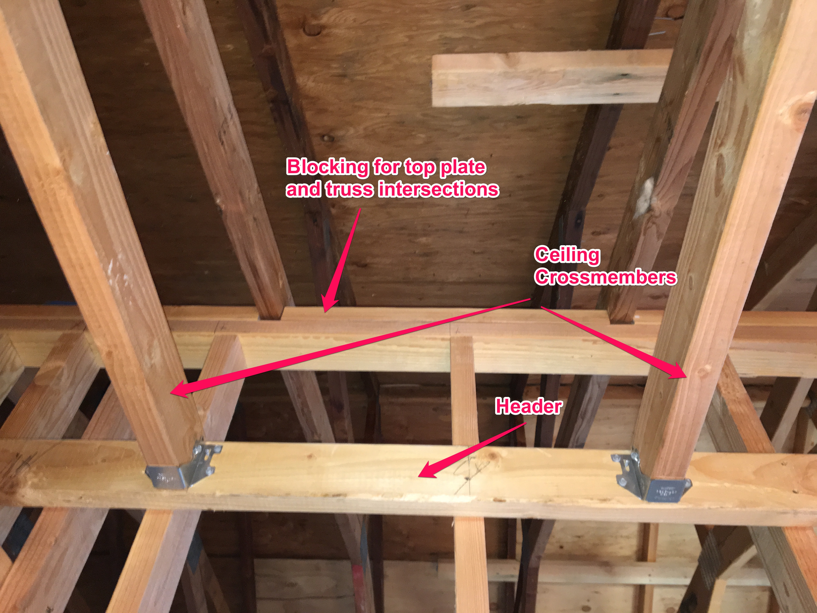
Finally, I had to install draft stops. The inspector pointed this out to me, so that was something I was unaware of, but once I figured it out, it was pretty easy. Basically, wherever you have a penetration through the sole or top plates of your framing, you need to seal the openings. The best way is to use polyurethane foam that comes in a can. You can get a one-use can with an applicator, but I found that hard to control, so I ponied up for a pro applicator, Worked much better, and I figured I’d be using it for other things.

Draft Stop

Draft stop for the data lines coming into the wiring closet. I also had to accommodate the gas line going up to the furnace, which is now in the attic.

So with the rough work done, it was time to put in one of the true infrastructure “upgrades” that I planned for this remodel: a residential fire sprinkler system. Stay tuned…..


Framing The Interior Walls

Now that the exterior part of the addition was complete, it was time to start work on the interior. The plans (that I designed and produced) had an “en-suite”, meaning an adjoining bathroom and other facilities. As a matter of fact, the design reflected my predilection for the “process” of getting ready for the day: do your business, brush your teeth and shave, shower, and then dress. Well, that’s my order. My wife’s order is not the same, so that meant that if we had a scheduling conflict, one could be in private for the “business end”, and the other could take care of the rest. But I digress….

At any rate, I had to construct the framework which meant erecting a wall, and then putting in false ceilings and compartments to define the elements of the space. I had to make the wall that separated the en-suite from the rest of the bedroom, and a couple of smaller walls that separated the toilet area from the shower and dressing areas. These two smaller walls also had to accommodate pocket doors. The framing for these walls was pretty standard (except for the pocket doors — more on that later), but I had to do some detail work to make sure that I had all the correct structural components figured out.

Interior wall construction is similar to exterior wall construction but if it’s a non-load bearing wall, you don’t have the same requirements, meaning that you don’t have to use structural grade lumber, and don’t have to have a bunch of connectors. However, because lumber and drywall are produced to standard dimensions, the rules on top plates, sole plates, and stud spacing generally apply. Other than applying exterior sheathing, the techniques for construction are exactly the same.

Step One: Measure and Mark. The best starting point for wall construction is to lay out the wall on the floor. Professional carpenters do this for all the walls at once because it both speeds the construction process, and  but more importantly, it ensures accuracy and minimizes mistakes because you can see if everything fits together when you transfer all of the plan dimensions to full scale all at once. Not that there were any mistakes in the plans, mind you….(!)

(A) Locate the interior wall from a convenient reference. I used the existing exterior wall and the interior wall end that I had to marry up with.

Tools required for layout. If you’re doing this solo, then you need a handful of finishing nails and a hammer to hold the end of your chalk line (which I have in my belt, but neglected to photograph).

Plan for the wall. I drew this custom from my model. Typically you’ll just have a plan (overhead) view and have to figure out all of the vertical stuff, and I could have probably just done a quick hand drawing, but I’m also the designer, draftsman, and engineer, so I can do it how I want.

Location of sole plate from exterior wall framing.

(B) Check for square. Never assume that any previous work is perfect. Anything you build will have

errors that slowly build up and must be corrected for at each step.

Check marks to make sure they’re square before you snap the chalk lines. This is 63 3/4″ from the exterior wall.

Measure a convenient distance along the exterior wall.

Calculate the hypotenuse of the triangle using the good old Pythagorean Theorem which you learned in middle school (you did, right?).

The moment of truth. Dead on.

Once square is confirmed, locate the other end of the wall out from the reference (exterior wall). Wall baseline measurements in place with nails for holding the chalk line. Marks are also made at the other end of the wall (not shown here).

(C) Snap baselines for the sole plate.

Wall baselines snapped.

(D) Mark the openings and intersecting walls. I needed to mark the entrance to the bathroom and the two intersecting walls that defined the toilet area. I ended up changing where the toilet walls were located to match where the drain was, and also decided to change the door swing to make it more ergonomic. Once you lay things out in full scale, you will find you will need to adjust. The plans are never (exactly) right!

The red marks indicate changing the location of the partition walls to match where the rough plumbing for the toilet came in.


I decided to change the door swing to better accommodate ergonomics for entry and exit from the bathroom.

Step Two: Make a kit. Once the lines for the sole plates are marked out with the door openings and intersecting walls, it’s time to start marking out lumber and cutting. The key to framing any wall is to carefully mark out where all of the studs/jacks/cripples will be on the sole plate, and then transfer those marks directly to the top plate. This ensures that the ends of each stud/jack/cripple will be vertically aligned, making the wall relatively easy to square up and put in place.

(A) Cut the plates to size.

16′ lumber ready for marking. I will only use two pieces for the wall plates (sole and top) and the third will be a header for the false ceiling inside the wall.


Measuring out the length of the sole plate.

I put the measurement on the lumber so I won’t forget!

(B) Transfer the marks from the floor layout to the sole plate.

Sole plate on baselines, ready for marking.

Marking where the header of the toilet enclosure wall will go. The marks are transferred directly from the layout on the floor.

(C) Transfer the marks to the top plate.

Sole plate and top plate clamped up for marking. You want to mark both at the same time for accuracy and efficiency.

Marking cripple studs on top plate. These will be transferred to the door header when framing up.

If you want a 16 oc spacing, you have to offset the first one from the end by 3/4″.

(D) Make a cut list. This is done by methodically going through each mark on your top and bottom plates and figuring out how many studs (vertical pieces of lumber) you need and of what kind. There are four kinds of studs:  Common (or just “studs”), Cripple, Jack, and King. Common studs are what you’ll have the most of. They are the height of the finished wall MINUS the thickness of the sole and top plates. For an interior wall with just one of each, that’s wall height -3″. With a double top plate, it’s wall height – 4-1/2″. In my case, the wall was going to meet the undersides of the trusses, which were angled to form the cathedral ceiling. So I had to use a plumb bob to find where the inside edge of the wall would touch the truss and measure from there.

Plumb bob lining up the edge of the wall to the truss. It’s actually pointing to the wrong line in this picture, (the correct line is the one on the lower right) but you get the idea.

Marking the bottom of the truss.

Mark on bottom of truss directly above the inner edge of the wall (i.e., the face of the wall towards the bathroom). Finish nail is in place to snap a chalk line.

Chalk line snapped on bottom of trusses to align the wall when it’s raised.

Back to the types of studs. Cripple studs are short studs that connect the tops/bottoms of wall openings to the sole or top plates. So, you’ll have a few of these wherever you have a door or window. In this case, I had a door and needed to place cripple studs between the door header and the top plate. Jack and King studs are what form the sides of the wall openings (windows/doors). The jack stud provides vertical support for the header while the king stud sits right next to the jack stud and provides stability to the header. The king stud is the same length as the other “common” studs but has a different name due to its function and location within the framing.

Door framing showing relationships between framing members. The cripple studs go above the header (where the hammer is). Note that the bottom of the door has the sole plate going right across. This will remain until after the wall is lifted and secured in place to make the wall assembly stiffer and easier to lift. It’s a simple matter to cut this out with a handsaw after the wall is up.

Once all of the various studs have been counted (and double counted), I put them into a table called a “cut list” to make sure that I didn’t leave anything out and that I had all of my measurements correct. I also put in the materials for the headers and the 4×4 header supports for the two smaller walls for the toilet area. Take some time to double check your work here because if you make a mistake and cut all your studs 4″ too short, you’ll have a lot of extra firewood and an unexpected trip to Home Depot.

Cut list. Makes it easy to get an assembly line going and helps keep track of where all of your parts are.

Cutting station. I couldn’t get my fancy (and too heavy) miter saw stand up here, so I improvised. Worked great!

All studs, cripples, jack studs, plates and headers stacked and ready to roll!

Step Three: Assemble the kit. This should be the easy part, right? Just separate your top and bottom plates, scatter your studs and arrange your headers and start banging away!

Kit components aligned on the floor, ready for assembly.

Well, not so fast. There are a few subtleties that bear mention when putting this thing together. First and foremost, you need to plan for a logical assembly sequence so that you avoid having to nail components awkwardly, or worse, have to disassemble a part because you couldn’t get to it. For this wall, I made several sub-assemblies so that I could accurately nail them together without interference from adjoining components. These sub-assemblies included the header, jack and king studs for the door, and header supports for the two walls separating the toilet area.

King and jack studs for door are pre-assembled. It’s a lot easier to face nail these two together when sitting flat then it is to try to bang it together when on its side and you have a floor and other studs to deal with.

Door framing subassembly with header, king, and jack studs. Also a partial assembly for the toilet wall header support (the one with the 4×4). I only nailed one king stud so that I could easily slide the header onto the support once the wall was up. I would then be able to nail the second king stud in place on the other side. This is a good example of thinking several steps ahead to avoid unpleasant problems in the future.

A good place to start is at one of the corners. I started with the sole plate.

Sole plate complete.

The other issue that you have to deal with are imperfections, both with your materials for the wall and the surrounding structures where the wall will go. Wood is rarely perfect. Some lumber can be badly warped. In some cases, you can take the worst pieces and use those for cutoffs, like cripple studs, where the warp won’t matter as much. Also, you can use warped lumber for the inner studs, where it doesn’t matter very much. Save your straightest pieces for the ends and the door framing, where that alignment matters most. You can also use leverage and beaters (sledgehammers) to “persuade” recalcitrant pieces of lumber into place.

Because of variations in the height of the floor (long story) I needed to put shims underneath some of the studs so they would be aligned with the plates.

Using a “cheater bar” to untwist lumber for nailing. I attached a 2×4 to the inside of the stud and then pulled like hell while I nailed the end to the top plate. I then removed the cheater bar.

Securing the top plate.

Wall complete and ready to raise!

Step 4: Raise the wall. Now it was finally time to raise the wall. Because it was inside the structure, I couldn’t use the wall jacks that I used for the exterior walls because the lumber used for the jacks would not fit under the ceiling. So I had to do this the “old fashioned” way with some helpers. The interior wall framing is lighter because it has no sheathing, and is also “flexible” meaning that I did not bother to perfectly square it up before I raised it. This is because it was going to fit between the floor below, lower truss chords above, and abut against an adjacent wall. So long as I had marks on the floor for the sole plate and marks on the truss chords for the top plate, and these two were plumb to each other, I could be reasonably certain that the wall would be plumb and in alignment with the rest of the framing.

Wall raised and in place.

Because the main wall intersected the slope of the cathedral ceiling, I had to make a few accommodations. Specifically I had to install blocking on the top plate between the trusses to lock in the top of the wall. See the following picture of the false ceiling.

Step 5: Finish the interior details: Lastly, I had to construct a false ceiling on the other side of the wall and add a couple of partitions. Since I wanted the toilet to be separate and isolated when necessary, I had to put in walls that accommodated pocket doors. Pocket doors require an entirely different framing system. There are many types of systems that use basic materials to do the framing, but from a DIY standpoint, I found it more expedient to just buy a kit. The instructions were pretty straightforward, and as long as you’re accurate with the measurements, it’s largely foolproof.

False ceiling assembly detail showing the header and the false ceiling cross members.

Hangers for pocket doors installed. The headers for the doors will rest on these and when the door kits are installed, these will form the walls for the toilet area.

Pocket door headers installed.

Pocket Door Kit Instructions. This is the easiest solution.

Pocket door installed. I couldn’t find a picture of the framework (!)

The last thing I did was to cut out that piece of sole plate that was interfering with the door. If you recall, I constructed the wall with a continuous sole plate to help hold it together when the wall was raised. Now that the wall framework was finished, it was time to clean up that little detail.

Door opening with sole plate in place. I’m going to take care of that presently.

Sole plate is now cut for the door opening.

Now that the interior framing is in place, it’s time to proceed to the next step: rough plumbing, electrical, and data lines.

Building a Paver Patio

One of my  “successful” DIY projects was a paver patio I built when I was living in Chesapeake Virginia. In fact, you can still see the results of my handiwork on Google Earth. The address is 1901 Shady Cove Ct. (if you want to check it out). Building a paver patio is DEFINITELY in the realm of DIY. The question is, do you want it do look like DIY, or do you want it to look professional? I always choose the latter. And I think that all serious DIY’ers aspire to create works that equal the quality of, if not exceed, those that can be professionally built. I guess that strays into the realm of “artisan”, but let’s keep the discussion on the practical side.

We start with the basics. Looking good is one thing. Looking good and lasting a long time is quite another. In my second attempt at building a paver patio, which happened to be at my current address, I took a few shortcuts. While the initial results were nothing short of outstanding (hey, this was the second time I was doing this, right?), over time the patio deteriorated. I didn’t put in a proper aggregate base, and I didn’t seal it, so the ants came in and undermined the sand under the pavers which caused the pavers to sink and the ants to rise up and threaten our very existence. Additionally, the level and slope did not provide proper drainage. I spent a lot of time and effort (and $) fixing the level and drainage problems, as profusely documented in other posts on this blog, but I want to now focus on slope.

It is important to make sure that the ground has at least a 2% slope away from the foundation of the house to allow for proper drainage and water shedding during a heavy rainfall. While we don’t get a lot of rain here in San Diego, when it comes, it comes in gigantic buckets. So my landscape has to be able to handle large rates of rainfall, as infrequent as they might be. A 2% slope is more than adequate, but how, exactly, do you do this?

Making an accurate slope starts with defining a reference point. In the case of a slope away from a house, the reference is, well, the house. Convenient references are typically siding or the weep screed on stucco. Since I have stucco, I’m using the weep screed. Because stucco absorbs water, the top of the finished grade must be at least 4″ below the weep screed. Adding 2″ for the pavers, 1″ for the sand base, and 4″ for the aggregate base means that the ground must be 11″ lower than the weep screed. That’s fine for the level at the foundation, but my drainage grates are 10′ away from the house (120″) meaning that I have to subtract an additional 2-1/2″ to from the 11″ to get the required 2% slope away from the foundation (120″ x 2% = 2.4″). This means that the ground must be 13 -1/2″ lower than the weep screed at the line of my drains.

Now, you have to transfer these measurements to the surface of the soil. You can use a tape measure to transfer the marks from the weep screed, and then use a line level to transfer that mark to the reference you’re using for the slope, and measure down from there. However, that’s not very accurate, and it’s pretty fussy, especially for a DIY’er. A far better method is to get a laser level and a grade stick. It used to be that these setups cost thousands of dollars. But now, you can pick up a good rig for around $375.00. OK, that’s not exactly cheap, and if you’re doing just one job, then maybe renting is a good idea. But if you are doing remodeling as a DIYer working alone, this will come in mighty handy. Plus, isn’t collecting cool tools part of the DIY experience? I can always justify the expense by how much I save in labor costs. But I digress. Here is what you need:

Laser level tools. Make sure you get a grade rod calibrated in fractional inches. Most surveying grade rods are in decimal feet, and that can be a pain to convert, unless you're a professional surveyor, in which case you don't bother converting and leave that to the other trades.

Laser level tools. Make sure you get a grade rod calibrated in fractional inches. Most surveying grade rods are in decimal feet, and that can be a pain to convert, unless you’re a professional surveyor, in which case you don’t bother converting and leave that to the other trades.

Onto the task of transferring these measurements. After a lot of thought, I came up the idea of pounding in grade stakes close to the foundation, and then doing the same where I wanted the low point of the grade to be (near the drainage grates). I would then connect them with strings, and I would have an accurate grid to which I could properly set the grade. The only problem was that if I used the calculated level of the ground, I would have to be fussing with marking and stringing at ground level. Totally a non-starter. What I came up with was to offset the level by 4″. This corresponds to the depth of the aggregate base which I plan on putting in. I would then use a wooden “block” that was 4″ in height to run along the string, which would establish the proper level of the ground with the correct slope.  Here is a video and some pictures.

Now that the building lines are set, I have to remove additional dirt to get to the correct level.

Now that the building lines are set, I have to remove additional dirt to get to the correct level.

Look at these dirt clods. I needed a pick to break them apart!

Look at these dirt clods. I needed a pick to break them apart!

More petrified potatoes. Fortunately, these are very popular as free giveaways on Craigslist. I don't have problems getting rid of these.

More petrified potatoes. Fortunately, these are very popular as free giveaways on Craigslist. I don’t have problems getting rid of these.

This shows how I graded to the lines. I ran my 4" block along the lines and then established the correct grade at the lines.

This shows how I graded to the lines. I ran my 4″ block along the lines and then established the correct grade at the lines.

I then eyeballed the grade and leveled everything out. Pretty nice, eh?

I then eyeballed the grade and leveled everything out. Pretty nice, eh?

Unfortunately while digging (again) I had some trouble locating previously buried services. This is a repair job of my blasting apart my pristine new greywater irrigation system. Fortunately I know how to fix this stuff.

Unfortunately while digging (again) I had some trouble locating previously buried services. This is a repair job of my blasting apart my pristine new greywater irrigation system. Fortunately I know how to fix this stuff.


Here is the truck used to deliver the 15 yards of aggregate base.

Here is the truck used to deliver the 15 yards of aggregate base.

And here is the aggregate base in all its 15 yards of wonderfulness. This is really going to suck.

And here is the aggregate base in all its 15 yards of wonderfulness. This is really going to suck.

Here is a cool video on how to tighten, and easily loosen, building strings.

Easy Building String Knot

Now that the proper grade is established at the ground level, the next step is to add the aggregate base. The best aggregate base to use, at least in Southern California, is something called “Class 2 Road Base”. This is a mixture of aggregates from 3/4″ gravel down to dust. Plus it had recycled concrete. And it’s cheap(er). Best of all it compacts to a very stable base which is perfectly suited to a paver patio. Because I had the true genius of using a 4″ offset for my building strings, “all” I had to do was to trundle in the aggregate base and make it level with my strings. However, all of my genius could not overcome the basic fact of having to muscle the 15 yards of aggregate that was required to fill my front and back yard to the required 4″. Once the aggregate base is in place, it MUST be compacted. The best way to do this is with a plate vibratory compactor that can be rented. The aggregate base that I’m using compacts really well because of the different aggregate sizes. It really makes a stable, sturdy base on which to lay your pavers. Here are some pictures of the finished product:

This is the fill all compacted. The orange beast in the foreground is the plate compactor. Also notice the wet say in the background. This tool is essential in making nice cuts for your pavers.

This is the fill all compacted. The orange beast in the foreground is the plate compactor. Also notice the wet say in the background. This tool is essential in making nice cuts for your pavers.

Side yard all nice and compacted.

Side yard all nice and compacted.

Front yard all ready for the next step. I'll be filling this with decomposed granite (DG) and will stabilize it with a goop which promises to be resistant to erosion. We'll see...

Front yard all ready for the next step. I’ll be filling this with decomposed granite (DG) and will stabilize it with a goop which promises to be resistant to erosion. We’ll see…

The next thing to do is to lay out the sand on which you’ll be placing the pavers. After doing some research on the Internet, I found a really nifty way to get it perfect. Obtain some 3/4″ PVC pipes, which have an outside diameter of 1″, and lay them down at 4′ intervals. Then dump your sand between the pipes and screed it off with a 2×4. The original video on the Internet showed an 8′ spacing, but they had 2 people working the screed. So I chose to shorten the distance to make it easier for a one-person crew. Working as one person sometimes requires a different approach than what a professional crew would do, so just “doing it like the pros” is not always possible.

One-person screed.

One-person screed.

Everything is now ready for actually laying the pavers. While this can be a big payoff, because it’s so easy as compared to setting the grade and leveling the aggregate base, you have to be careful to set up that all important first course as accurately as you can. Once again, we need some reference points, and the most common one is the foundation of the house. In my case, since the patio occupies the entire back yard, I chose to use the corner of my foundation. The first bricks to lay will be the brick edging, which are bricks that are set perpendicular to the wall. For the corners, I used some 8″x8″ paver blocks, which made the corner transitions easier than cutting up 4″x8″ bricks on the diagonal. More of that to come. Now to set the pattern which you’re going to use for the “field”. Many patterns (basket-weave. running bond, 90º herringbone) should fit right along your edging, and you can merrily brick away. However, I chose to use a 45º herringbone pattern because (a) looks really cool, (b) aligns with the cardinal compass points relative to true north on the property, and (c) is a bit more challenging.

To line up a 45º pattern, the first thing to do is to set up a building line with some masonry string and blocks. This line needs to be parallel to the edge you’ll be working, and should be offset such that the filler bricks are relatively easy to cut and fit. I’ve seen some videos of how to set this up on the Internet, and while watching the process is instructive, these videos miss the obvious when it comes to determining the offset. It’s really quite simple: since the bricks will intersect the edge at a 45º angle, you’ll want to cut off the corner of a brick so you can flip the pieces around and complete the pattern. Here is a diagram:

Diagram of how to set up the first course.

Diagram of how to set up the first course.

A closer look at the diagram shows that the offset is the hypotenuse of a 45º right triangle, whose two legs correspond to the width of your brick. The hypotenuse is the square root of the sum of the squares of the legs (Pythagorean theorem, yes?), So since my bricks are 4″x8″, the offset is √(4² + 4²) = √(16+16) = √32 = 5.65. That works out to 5-5/8″. (If you really want to be nerdly, the closest fraction is 21/32 which is right between 5/8 and 11/16, so you could use your tape measure to get spot on, but in reality, 1/8″ is pretty good.) Why do I discuss this? Because I’m a nerd. And proud of it! That bit of mathematical nuance out of the way, it’s time to lay some brick! Take your bricks and align the corners diagonally with the mason’s line. You want to lay a fair number of bricks to establish a good course to build from, as shown in the picture. I set about 10 pairs (20 bricks).

Now we get to a point where we have to start thinking about the order of things. Specifically, you need to think about how you’re going to set the sand base, then lay the brick, without stepping in the sand base (which defeats the purpose), or disrupting the bricks that you’ve already set. You can (indeed must) walk on the placed brick, but you must step gingerly so as not to disrupt the bricks on the edges. So the brick path you step on needs to be at least 5-6 courses wide. You can start from one edge and build out until it’s wide enough, and then you’re home free.

Stepping Stones. Lay enough brick so you can step on it (carefully) and work your way out.

Stepping Stones. Lay enough brick so you can step on it (carefully) and work your way out.

One of the critical observations in doing masonry work is to realize that masonry is the art of adjustment. Constantly. Bricks are not exactly the same size. Foundations are not exactly straight. So, one has to constantly compromise. In laying this particular herringbone pattern, I noticed that the bricks tended to become misaligned, probably due to the fact that the bricks came in contact with the edging at their corners. This meant that only a slight misalignment in the angle of the bricks will make a big difference. The way to notice this is to look at the gaps between the bricks. If there are excessive gaps, then it is likely that the bricks are misaligned. This is where your rubber hammer becomes your friend. Simply tap the edges of the bricks and they will tend to lock together and self-align. To a point. If you’re not vigilant, then things can get away from you and you might have to pull some of the bricks up so you can align them. Bottom line: constantly pay attention!

It turns out that laying the pavers, as whole bricks, is only half the job. The other half comes when you have to cut the bricks to fit along the edges and any other protuberances, such as post foundations and drainage grates. This is where a diamond blade wet saw comes in handy. Although one can dry cut the bricks with a grinder, the wet saw makes the cuts much more accurately, resulting in a very nice, professional look. The cost of renting this type of saw is totally worth it, especially when compared to the effort you will expend in putting all of the pavers in. The technique is to fit a brick where it would normally go, and then mark where it contacts the edge with a sharpie. Turn the brick over, draw a line between your two marks, and you now have your cut line. I also number the cuts so I can cut in batches to save time, yet keep all of the pieces organized. You’d be surprised how much they all start looking alike! Remember — mark the BOTTOM of the brick. Having a bunch of numbers on the top of your bricks will elicit some uncomfortable questions by your guests after you finish.

Step #1: Line up your bricks.

Step #1: Line up your bricks.

Step #2: Mark where the brick intersects the edge.

Step #2: Mark where the brick intersects the edge.

Step #3: Connect the marks to make a line.

Step #3: Connect the marks to make a line.

Step #4: Number your bricks so you'll remember where they go.

Step #4: Number your bricks so you’ll remember where they go.

Step #5 Cut the bricks. See how handy the numbers are?

Step #5 Cut the bricks. See how handy the numbers are?

Step #6. Set the bricks in place. Looks nice!

Step #6. Set the bricks in place. Looks nice!

Now that the bricks are in place, they should be set into the sand base. This is best done with a plate vibratory compactor. This is a little like a lawn mower, except that it’s heavy and has some weights that rapidly spin, causing the plate on the bottom to buzz in a heavy manner. This is, perhaps, one interpretation of getting “heavily buzzed”. At any rate, the bricks will settle nicely into the sand base and start to lock up with each other, stabilizing the entire assembly. That’s all good, but in order to completely stabilize the structure, you must add sand. These pavers are specifically designed to have small (1/8″) gaps between them — in fact, there are little tabs on the sides of the brick to optimize this spacing and keep it uniform throughout. Because the gap is small, and the friction of the sand is what is used to lock the pavers in place, it is important to use “joint sand”, which has the right grain size and sharp edges. The process is to spread the sand all around, sweeping it back and forth a bit to get it to go into the gaps, and then take the plate compactor and run it over the bricks again. This will shake the bricks and the sand will rapidly and completely fill the gaps. (Heavily buzzed with “joint” sand — hmmm…. maybe that’s what makes them act like bricks.) You’ll want to sweep and vibrate one more time to make sure the gaps are filled all the way to the top. You will likely now have some excess sand on top, so it will need to be swept off. I used the extra sand to make a sandbox for our outdoor cat, Tiger.

Here is our outdoor cat, Tiger, in the supervisory mode. He is a feral cat that we tamed, and he comes in to eat and when the weather is bad, but we could never litter train him. So....

Here is our outdoor cat, Tiger, in the supervisory mode. He is a feral cat that we tamed, and he comes in to eat and when the weather is bad, but we could never litter train him. So….

Tiger's Toidy. A pristine sandbox in a secluded, private location. It pays to be a cat!

Tiger’s Toidy. A pristine sandbox in a secluded, private location. It pays to be a cat!


Finally, the last step: sealer. Sealer is important because (a) it penetrates the sand, discouraging ants and other bugs from coming up through the gaps between the bricks, and (b) penetrates the surface of the bricks to make the cleanup of spills, including such things as grease from your grill and bird poop, much easier. Putting on the sealer was not particularly difficult, but it was important to flood the bricks, and especially the gaps, to get good penetration. I used a roller attached to a pole and it worked pretty well.

This particular job took a lot of time, particularly in some unseasonable heat, but I took some vitamins and had a few extra cups of coffee, so the following video outlines the process from start to finish.

As a bonus, I now have completely cleared my driveway which, for the past 18 months, has served as a lay down area, particularly for the bricks and sand I harvested from the original patio. I finally feel as though my outside projects are near conclusion. Here are some more pictures:

Driveway with all the junk and lay-down for the patio. I removed the patio bricks 18 months before and they've been sitting there until now when I could reinstall them.

Driveway with all the junk and lay-down for the patio. I removed the patio bricks 18 months before and they’ve been sitting there until now when I could reinstall them.

After 18 months, the driveway is clear and I can now park my cars! Unfortunately, this is a temporary situation as I will be starting on the inside of the house and will need this space for another lay-down area. :(

After 18 months, the driveway is clear and I can now park my cars! Unfortunately, this is a temporary situation as I will be starting on the inside of the house and will need this space for another lay-down area. 😦

So, the next few steps will be to finish off the outside, and that begins with a terrific outdoor space called a “catio”. More to follow….

Getting Ready For A Concrete Pour

Things are beginning to shape up in front, and one of the final “projects” was going to be to pour the concrete. This is DEFINITELY a job for a professional crew — NOT DIY! I know this from harsh, personal experience. Oh, I know, the videos make it seem really easy, but trust me, striking off a mound of concrete with a screed is hard, messy work, and is actually quite comical if it’s just you and your wife doing it. OK, I’ve done a couple of small sidewalks, but this job is way too large and intricate to trust to anybody but a professional crew. Hey, at least give me credit for knowing the difference!

Be that as it may, I had my plans, so I know what I wanted to do. Well, at least I thought that I did at the beginning. More on that later. The fact is that a dedicated DIY’er can do essentially all of the prep work. This is quite a lot of work, it turns out, and while you may get some benefit of saving some money, the biggest advantage for me was giving the concrete subcontractor a lot of flexibility with the schedule. If you have a pro do the whole job (demolition, site and grade prep, base fill, building the concrete forms, and setting out the remesh), then you’ll have to wait several weeks until the schedule is clear for a multi-day (or week) job. If you do all of the work, it’s a 1 day job of pouring and finishing the concrete, which can be scheduled more easily. Now for all of that prep work.

Demolition was done previously, per several of my previous posts. And, although I did a reasonable job of getting the grade set correctly with the steer skid, I still had a fair amount of cleanup to do. The skid steer doesn’t get into the corners, plus I had to get some stumps ground after I had completed the initial excavation. Plus the rains over the winter (such as they were) ended up “displacing” some dirt which had to be “re-placed”. In other words moved around some more. I ended up barrowing out about 4-5 yards of dirt to the back.

Will I EVER get rid of this dirt?

Will I EVER get rid of this dirt?


The next thing to do was to set up a base. I had a choice between 3/4″ gravel and “class II  road base”. I decided to use gravel because I though it might be better, but it turns out that class II road base is what is typically used around here because gravel is used for areas where frost heave is a problem, and you want something to absorb the resulting ground motion. Road base is less expensive (!), and since it compacts way better, I plan on using it as the base for my brick-on-sand patio. So I find this out too late and I now have 7 yards of gravel to chuck  and spread around. C’est la vie! Fortunately this went reasonably quickly. The only hiccup was that I had to somehow figure out a way to get wheelbarrows of this stuff to the back while navigating around previously installed drainage pipes that were annoyingly protruding from the ground. My solution was to barrow a pile of gravel around the drains and then take some plywood and make little ramps so that I could gingerly push a wheelbarrow with several hundred pounds of gravel through the maze that eventually lead to the back yard. After all was distributed, I rented a plate compactor to give a good solid base.  Because the compactor wouldn’t fit into the corners, or around some of the obstacles sticking up, I had to use a hand compactor to get everything nice and tight.

That there is a cubic butt ton of gravel to move!

That there is a cubic butt ton of gravel to move!

Chucking gravel from front to back. Note the plywood highway.

Chucking gravel from front to back. Note the plywood highway.


I used a pile of gravel and some plywood ramps to navigate around the drain grates that were sticking up. I ended up raking the gravel level as i worked my way back, so it ended up all good.

I used a pile of gravel and some plywood ramps to navigate around the drain grates that were sticking up. I ended up raking the gravel level as i worked my way back, so it ended up all good.


Front entrance gravel all level and compact. Ready for the forms.

Front entrance gravel all level and compact. Ready for the forms.


While I was gearing up to move all of this gravel, I also had to buy lumber for the forms. So, I woke up early on a Saturday and headed over to the local Home Depot. Alas, it was raining, so it promised to be a mucky day outside. As I drove into the parking lot, I saw that the rental truck was conveniently parked, so I assumed it was available. I loaded up a bunch of lumber (plywood, 2x4s.), paid for it, and tried to rent the truck. I was then told it was out of commission for some obscure reason. Since my mood sufficiently sour to begin with, I vented my frustration. The customer service people were very nice, let me have my say, then proceeded to help me out with a free delivery. How good is that? So, shame on me for being a dickhead, but good for the Home Depot folks. I sent their boss a nice e-mail apologizing for my brief outburst and profusely thanking them for their excellent customer service. At any rate, I come back to the house and discover that my brand new wheelbarrow has a flat tire that will not succumb to mere inflation. So it’s back to Home Depot to get a flat-free tire. I guess it just was going to be one of those days….


My new wheelbarrow with a flat tire. Come on!

My new wheelbarrow with a flat tire. Come on!


Next was the forms. With my previous experiences with concrete, getting the forms right was always a challenge. So this time, I wanted to make them very sturdy and straight. I used 1/2″ plywood and made a frame of 2x4s to support the plywood so there would be no bending. The 2×4 frames also gave me something solid to work with so when I drove the stakes, I would be using the forms as the guide. The contractors who came out to bid basically said that this was overkill, and they may have been right. But as a DIY guy working alone, I think this gave me the best result and minimized the amount of fussing around to get the forms aligned and in place.

Frame for the form. I had to eventually rebuild this one because it was too large, but you get the idea.

Frame for the form. I had to eventually rebuild this one because it was too large, but you get the idea.

Detail of my forms. The corners are bolted together with braces that pull everything tight and square, and make disassembly very easy. Too bad I won't be using these again.

Detail of my forms. The corners are bolted together with braces that pull everything tight and square, and make disassembly very easy. Too bad I won’t be using these again.


Bottom of plywood on form extends down to allow for concrete to flow between levels to allow a monolithic slab without a lot of fuss in removing the form to finish the faces.

Bottom of plywood on form extends down to allow for concrete to flow between levels to allow a monolithic slab without a lot of fuss in removing the form to finish the faces.


One of the nuances of my design was that I wanted to place can lights within the concrete to provide lighting for the steps (as a safety feature). Although the lights that I chose were rated for casting in concrete, in the long run, that is a bad idea because when (not if) they fail, you’ll have to tear out the concrete to get to them. No thanks. So, my plan was to construct plywood molds that would result in a perfectly sized recess that I could fit the lights into. Additionally, the molds had a hole that accepted PVC conduit, so that I could run the wiring between the boxes and back out through the wires that I had cleverly routed around the house while I was digging the drainage lines to supply the power. This is 12v lighting, so no problem with running the wires adjacent to where water might be. However, on the back porch, the lights needed to be located near the top of the slab. This could be problematic with cracking, so I added a 1×1 wire mesh reinforcement with material I had left over from a previous project. I also knocked down the sharp edges of the plywood boxes to minimize stress concentrations. My hope is that, with these little details, plus the fact that I am going to tile over these fragile areas, will make everything all right.

After I had set up the forms, I and my wife had a good chance to look at what the final result might be and, you guessed it, we were having some reservations. So, we took a step back, and perhaps some steps around, and started to actually walk through the expected traffic patterns. After a few iterations, it became obvious that we had to change things around a little in the front, and that is one of the advantages of DIY. You really can change things at almost the last-minute without a great impact on cost or schedule. Had this been an agreed upon design and had I already had a contractor doing the work, changing this stuff would have been out of the question. Of course, perhaps my design was not so good to begin with, and maybe a pro would have come up with the right answer in the first place, but what fun is that? I also had to re-design (and re-build) the forms to have the proper height above the finished concrete surface and provide a gap underneath so that the pour could be continuous, resulting in a monolithic slab. Good thing I had ordered some extra lumber!

The front landing is disjointed and not ergonomic. It looked better in the model and plans.

The front landing is disjointed and not ergonomic. It looked better in the model and plans.

Just doesn't look right.

Just doesn’t look right.


That's more like it! Nicely balanced and allows access up the ramp (on the right), from the driveway apron (on the left), and from the garage.

That’s more like it! Nicely balanced and allows access up the ramp (on the right), from the driveway apron (on the left), and from the garage.


While I was doing all of this, it was time to get some bids for the work. I had a number of folks come by, and each was very helpful and offered some advice as I was finishing up. One comment was pretty much universal: “Fill in the areas where you have deep concrete (e.g. the back porch and front landing) with materials that are less expensive than concrete. Well, it turns out that I had a big pile of masonry detritus  accumulated from my previous work, so it was a no-brainer to chuck that stuff into these areas, if not to save money, than to just get rid of the stuff in a manner that did not involve surreptitiously dumping this crap into the residential waste stream over a long period of time. Which is my normal modus operandi. I learned this from my wife.

Finally, the re-mesh. This is a welded wire mesh that is used to provide reinforcement in the concrete. It is made of large gauge (#6) steel wires that are spot welded together to form a  6″x6” mesh. You can buy these in flat sheets of 5’x8′, but that is much more expensive than buying a 150′ roll and cutting it yourself. Of course, I did the latter. I had previously purchased a heavy-duty wire cutter (essential for this work) and set about unrolling the beast and nipping off sections so that they fit where I needed to put them. I ended up with a number of relatively small pieces because (a) they were easier to make flat — the roll has some “memory” so you have to bend it a little to make it lie flat — and (b) they were easier to handle and place where I needed them.

Back porch ready for the pour. Can you see the masonry detritus poking through the gravel? Also a good look at the forms and reinforcement for the can lights.

Back porch ready for the pour. Can you see the masonry detritus poking through the gravel? Also a good look at the forms and reinforcement for the can lights.

Left driveway apron all ready for the pour.

Left driveway apron all ready for the pour.


PVC electrical conduit is supported by rebar stakes so that it won't bend when the concrete is poured over it.

PVC electrical conduit is supported by rebar stakes so that it won’t bend when the concrete is poured over it.

Service sidewalk all ready. I'm replacing the square grates with round ones on the advice of the subcontractor to minimize cracking.

Service sidewalk all ready. I’m replacing the square grates with round ones on the advice of the subcontractor to minimize cracking.


Now everything was all set and the bids were in. It was time to choose a subcontractor. I chose a person who (a) provided a reasonable price (part of my day job is cost estimation, so I knew what the price range should be), and (b) would provide a schedule (e.g., meeting time, estimates), and stick to it. I believe the latter is a key indicator of future performance.

I’m meeting with the subcontractor tomorrow, and with luck, I’ll have the concrete poured by the end of the week. Wish me luck!

Happy New Year! Reflecting on 2014 and Looking Forward to 2015

The turn of the year is always a good time to reflect on the past year and look forward to the next. It’s a common demarcation point, and it occurs when we’re collectively given the time to reflect and plan, according to our nature. I know what you’re saying” “If you’re in retail, or emergency services, or in the military on deployment, the maybe I’m not given the time.” However, I think because of the time of year, everybody is doing it, and you can’t help yourself. Actually, serving your customers, community, or country can have special meaning at this time of year.

OK, well maybe not so much in retail.  As they say, anybody who says there are “No stupid questions!” has NEVER worked in customer service. You know, retail is a dang hard job, and I truly appreciate everybody who helps me when I’m shopping.With a smile and a kind word, you will always get superior customer service! All you have to do is to distinguish yourself from the a**hole who decided to take out their frustrations on some poor, underpaid retail associate who is constantly bombarded by yet another a**hole! But you have to remember to take the time to take the survey and say nice things. If you REALLY want to reward good customer service, then have the presence of mind to remember the name of the person who helped you, and then take the time to make a positive comment  on the survey, or the website. These people get promotions and monetary rewards for this kind of stuff. So, the lesson is: Be nice, and when you get good service, make sure you tell the boss!

Where was I?

Reflections on 2014: I had been planning my remodel since 2012, when my lovely wife and I started discussing concepts and the things that we really wanted out of  life, and how our home would reflect that. At the beginning of 2014, I had finished detailed planning and had drawings that I thought were good enough to submit to the city building department for approval. 8 months later, after 3 revisions, I finally got the building permit! Actually, I didn’t wait to get the building permit do start work. I knew that I needed to take out my patio in back, and I wanted to save the bricks and sand. That was a major undertaking which filled the dead time in between the review of the latest plan revision, and answering the comments for the next plan revision. Once I got the building permit, I started in earnest, with site demolition, excavation, and installation of underground services.

What I learned:

  1. If you don’t follow the prescribed approach in the codes, then you will have to have a licensed engineer sign off on your plans. For a small job, it’s not worth it (and they were kind enough to tell me that). Learn the codes and follow the prescriptive approach.
  2. Take each “rejection” as an opportunity to improve your design. I can say that my plans have been significantly improved by having reworked them for the building department.
  3. Detailed planning helps you build faster. My plans have speeded up my work (thus far) in ways that I could not have imagined before.
  4. Detailed planning does not account for everything. Inevitably, you run into unexpected obstacles. The fittings don’t fit like you expected. You need to change the routing of the conduit to account for other buried services. Remain flexible and adapt. “No battle plan survives first contact with the enemy.” (Field Marshal Helmuth von Moltke.)
  5. Know when to quit for the day. Something my dad taught me.  This is a big project and you have to know your limits. If you push too hard, then quality suffers. It’s OK to have goals, but sometimes (OK , frequently), the goals are too optimistic. There are only so many hours in the day, and you need to take care of yourself. So know when to quit for the day, and make sure that you leave enough time for clean up!

Goals for 2105:

  1. Don’t get injured. Building can be dangerous if you’re not careful!
  2. Keep my job. Don’t get too involved in the remodeling at the expense of the day job. Yes, I still have to pay for all of this somehow.
  3. Go to Smithfield, VA for my  wife’s 50th high school reunion.
  4. Finish the site work. I’m optimistic this will be done by March. But who knows?
  5. Move out of the master bedroom, and do the demo.
  6. Build the addition and close in. I’m hoping by July-August. Before the rains come in any case.
  7. Install A/C. That will be contracted out.
  8. Install a new roof. Also contracted out.
  9. Re-stucco the front. Yet more contract work.
  10. Paint the house. Did I mention contract work?
  11. Install new electrical service. This will be all me. Wish me luck!
  12. Don’t take the remodeling too seriously. Yes, it’s important to have goals and to work hard to achieve them, but in the end, this is supposed to be rewarding and it’s important to take pride in one’s accomplishments. Otherwise, I’d be hiring somebody to do all of this!

I wish all of you a very happy New Year, and I hope that you continue to follow my blog. I’m working on an epic post for digging ditches!  Stay tuned……

Home Fire Sprinklers — Why I Did It

When I was fiddling around in my “research” phase of what it would take to make my home compliant with contemporary standards, I stumbled across the requirement (in California at least) to have new construction homes be equipped with a fire sprinkler system. Being a veteran of the Navy, where there is a fetish about fire protection and safety — think about it, you’re surrounded volatile fuels and explosives in the middle of nowhere — it, needless to say, piqued my interest. I found out that IF you are involved in a fire (unlikely because I have been careful about minimizing the root causes of fire), then the statistics show that protection with a residential sprinkler system increases your survival rate by 80% and decreases your property damage by 70%. How could I not continue? Did I mention a fetish?

It turns out that installation of a residential fire sprinkler system is within the DIY realm. If you’re trying to go with a “modern” plumbing system, which has all sorts of headers and networks and PEX pipes, then it’s probably not DIY. If you don’t know what PEX or a networked plumbing system means, then it’s DEFINITELY NOT DIY. However, if it’s just a retrofit or a new construction, you can install a simple “tree-branch” design.

A “tree-branch” design is simply a source of water that has runs and branches to distribute the water to the individual sprinklers. The basic design mimics the design of a standard plumbing system. The source of the water needs to come from the main water supply to the house, and then branches off before the supply to the rest of the domestic water system. The sprinklers can be thought of as a “complimentary” plumbing system. So, if you can install plumbing using CPVC (Chlorinated Poly Vinyl Chloride) pipe, you’re GTG with a DIY installation. Except…..

There is a pesky requirement called a “hydraulic calculation” which involves a litany of limitations and specifications which, if followed, will ensure that your sprinkler system will spray the correct amount water over the area that it is designed to cover. There are a lot of variables, and the interaction of these variables (e.g., pressure, flowrate, pipe diameter, K-factor) can be intimidating if not fully understood.

FORTUNATELY (for me), this is right up my alley. My studies in chemical engineering involved fluid flow, so I had a good background in what the calculations were all about. I dug back into the recesses of my tiny brain, and , with the help of Wikipedia, reconstructed the seldom used  neural synapses to come up with a spreadsheet which helped me figure out the required water pressure at the street main, and the required water pressure of my design. So I called the water authority to get the pressure at my residence (105 psi) and I went merrily to work. I submitted my design, and got told that it was F/U.

First, the assumed pressure was wrong. I had to submit a request for the available water pressure at worst case conditions. It turns out that the fire department and water authority have this dance figured out. I was just not invited to it. Bottom line is that I had to request a “residual” pressure base on worst case conditions. Once I received that, I was back to ground zero. Second, I was not properly accounting for the pressure at the “second” sprinkler. Code requires that whenever you have two or more sprinklers in the same room (compartment), then you must use the most limiting flowrate from two of those sprinklers. I had to lick my wounds and remember the lessons that I learned (and apparently forgot) in my sophomore fluids flow class, and revise my handy-dandy spreadsheet to make it reflect reality.

With the new available pressure, and the right methodology with my spreadsheet, I had to re-do the entire design. In the end though, I actually was able to make the design easier and less expensive to install. The key was to make the k-factors similar. If you don’t understand what I’m talking about, then maybe you shouldn’t be designing a residential fire sprinkler system.

The upshot is that my sprinkler design was approved today. I’m actually quite proud of it because the majority of designers plug their designs into a computer program which tells them whether they are right or not. I did the calculations by hand, so I know that the design will work because I understand the underlying principles. OK, I used a spreadsheet, but I had to put the Hazen-Williams formulas in. I’m sure that if you contract a designer to provide a sprinkler plan for you, that it will be correct and will work just fine. It’s just that the designer won’t know exactly why. Let’s just keep that as our personal secret.

Here is my advice (for what it’s worth):

  • Get a residential fire sprinkler system. The cost is more than worth the peace of mind and the protection it offers your family and your home.
  • If you’re DIY, but perhaps not so interested in the nuances of hydraulic calculations, then try to hire a designer who will give you plans. Having said that, you’d better understand some of the nuances of fire sprinkler installation. There are very specific requirements for the mounting of the supply lines and sprinklers so that they don’t jump around when they get activated.
  • If you’re interested in the design, here are some references:

Residential Fire Sprinklers

Fire_Sprinkler-Installation_Instructions-English

ResidentialSprinklerInstallationGuide

Here are my plans:1370 BFD Fire Supression R 2.5

And the spreadsheet for the hydraulic calcs: 1370 BFD Hydraulic Calculation Worksheet CPVC

OK, I know I’m a geek at heart. I really do love to design and to manifest my ideas, in terms of numbers and letters (in the correct sequence) so that they can be created in the physical world. This is what I’m all about, and this is what I hope you can see as I take my next steps on the DIY highway.


P.S.  Did you notice that “Why I Did It” contains DIY backwards?

🙂

Irrigation — And How A Project Expands

This past week, I’ve been working on gutting my landscape. The reason for this is because the first order of business is to install a site drainage system. The reason this is first on the list is because I have to excavate in order to install my upgraded electrical power line from the power head on the street. I then have to cover it up and pour concrete because that is where I am going to place the temporary storage box for all the household crap I have to move in order to vacate my master bedroom to build out the addition. A real Chinese puzzle.  But I digress. So, if I’m going to excavate and break up concrete and hardscape, I better do this once. That means that I have to plan for ALL underground utilities, being it 12V lighting, drainage, or irrigation.

When I started looking into irrigation, I wanted to make sure that I was making a very conservative plan as water, especially for irrigation, is a scarce resource here in Southern California. My studies revealed that the two approaches which made most sense were drip irrigation with a xeriscape, and use of grey water from the laundry. First the xeriscape.

The idea of a xeriscape is not new. There are several high quality example gardens in our area, and we have visited them on more than one occasion. The idea is that you provide some drip irrigation to start the plants out, and as they mature, they require less and less water. Plus, drip irrigation is very efficient as it waters the roots directly, as opposed to spraying water all over the place and having the excess run down the storm drain. Let’s face it: if you live in Southern California, or any other place which is subject to drought, then you should be ashamed of yourself if you have spray irrigation. Especially if you have a lawn. If you like the expanse of green, then get artificial turf. The modern and smart way to landscape is with drip irrigation and water conservative plants.

The best reference I was able to come up with was a website called irrigationtutorials.com.  The person who writes this is a professional landscape architect, and his information is very detailed and practical. Regardless of what irrigation system you choose, you would do well to visit this site and to peruse, if not read thoroughly, what he has to say. I learned a TON about what to do, but more importantly, what NOT to do. Pay particular attention to the section on backflow prevention. This is serious stuff, especially if you don’t want your drinking water contaminated with whatever happens to be on or near your drippers. After all, animals, both domestic and wild, have to do their business somewhere!

The other thing I discovered, and I am STOKED about this, is the use of grey water for irrigation. Grey water is waste water from your house that is not sewage, e.g., not from your toilets. So, anything from your sinks, showers, dishwasher, or laundry, is considered grey water. Now, if you’re ultra conservative, you could set up a system that uses ALL of your grey water for irrigation purposes. But some of this requires permits and professional design. However, there is a low-cost DIY approach: using the effluent of your washing machine. Your washing machine uses a lot of water per load. If you have a top loader, then it’s 40 gallons per load (20 gal wash and 20 gal rinse). Even the high-efficiency front-loaders are 20 gallons per load. So, why not put all of that water to use in irrigating your property? The answer is that it’s pretty simple and definitely within the realm of a DIY project. First, there’s typically no permit required. Second, it’s relatively cheap. All you need is a 3-way valve, a vacuum breaker, some PVC pipe and fittings, some materials to make a bunch of mini-dry wells (perforated pipe, gravel, and circular pavers), and some inexpensive valves to regulate the flow such that you have an even distribution of water. There are some regulations that you have to be aware of, such as property line setbacks and having sufficient surface area to distribute water so that it doesn’t pool or overflow, but these requirements are spelled out very succinctly in a number of on-line articles. The best one is a manual that was produced by the city of San Francisco, CA (San Francisco Grey Water Design Manual) that is a very comprehensive guide. It includes detailed instructions for installation of a DIY laundry effluent grey water system. In my jurisdiction, Chula Vista, CA, the city took (plagiarized) elements of this manual for local guidance. So, if you care about water conservation and are in an area where drought is a concern, this something very simple and do-able for the average DIY.

The San Diego County Water Authority published a good guidebook on how to design a “water-smart” landscape (here). Additionally, the City of Chula Vista posted some professionally designed xeriscapes. Here is the link, but for some reason, it’s not working at the moment I’m writing this, so I’ve posted one of the plans here: wildlifefriendly-irrigationplanwildlifefriendly-planwildlifefriendly-plantimageswildlifefriendly-concept,

So, this was an expansion to the original project, but for several reasons, I think this is the way to go. I’ll have more details about my site plan in future posts.

Architectural Design — The Addition, and Fixing The Roof Leak

One of the major reasons I started this project was the fact that I had an annoying leak from the roof that was making a big stain on the ceiling in my living room. The leak really comes from a second floor balcony which is adjacent to the master bedroom. The design is poor because water accumulates from the roof and concentrates in the balcony, and there is no easy way for the water to run off. So it stays in the balcony and ultimately leaks onto the porch, the garage, and the living room. I tried three different ways to fix the floor of the balcony (tile, flat roofing, and rubber membrane), and none of them worked. In looking around the rest of the neighborhood with houses of similar design, I noted that they also had the same problem.


BALCONY DESIGN_2

ORIGINAL BALCONY DESIGN

So another approach was necessary. Fortunately, a few of the houses had a modification that put a valley roof directly above the porch. I asked the owners if that helped and they all said that it completely solved the leakage problem.

ROOF OVER FRONT PORCH-1

ROOF OVER FRONT PORCH 2

That being said, the balcony itself was just wasted space. It was hot in the afternoon because it faces South West, and it has an expansive view of the garages of my neighbors across the street. Not exactly a place where I’d hang out and relax. So, to make more out of the space, I decided to see what it took to completely eliminate the balcony and expand the master bedroom.  There were some homes in the neighborhood that had done that, but I didn’t like the outcome because they didn’t fix the leakage problem. Plus, I wanted to reconfigure the windows to provide better air flow and noise mitigation, and I wanted to rearrange the master bathroom and closet to provide a more open floor plan.

EXPANDED MASTER BEDROOM

EXPANDED MASTER BEDROOM


So, I looked at my original floor plan, and went back to the type of functionality we wanted. We decided to utilize the new space in an open manner, swap the location of the toilet and lavatory, make a small “room” for the toilet area with folding doors, and enable a natural flow from the bathroom to the dressing area. The dressing area would be open, yet private, and have some nice light coming in from the new windows. We also have some room for a sitting area and our desks. Simple and straightforward, but it looks pretty nice. At least from the plans!  I think it meets our requirements for making the most out of wasted space and provides a permanent fix for the roof leak.

Here are the plans:


ARCHITECTURAL

ELEVATIONS


ARCHITECTURAL DESIGN

EXISTING 2ND FLOOR

ARCHITECTURAL DESIGN

NEW 2ND FLOOR

Electrical Design

As with any other design, electrical design begins with your requirements. Lighting requirements, which I discussed in a previous post, will dictate the locations and types of switches and circuits. But one also must consider the other electrical needs of the house. This includes electrical outlets,  appliances, HVAC (Heating, Ventilation, and Air Conditioning), and specialty circuits such as an electric car charger or a stair elevator. When considering the electrical requirements of my remodel, I also wanted some room for future expansion to take care of needs that aren’t yet specified. In an older home, this typically means that you’ll have to upgrade the service going into the house. More on that in a bit. Here is the list of requirements that I came up with for my remodel.

  1. Significantly expanded permanent lighting to be controlled with switches from convenient places.
  2. Additional outlets for the den (entertainment center) and kitchen.
  3. Dual electric car chargers.
  4. Air conditioning system.
  5. Additional outlets in garage to support a smart home wiring closet

Now at this point of the design, we start to get on thin ice when it comes to a DIY job. You will have to start making design decisions and tradeoffs which are going to be influenced by code requirements, and unless you have some background and experience with electrical design and code requirements, it might be a good idea to enlist the help of a professional. In my case, I have an engineering degree, so I have a good handle on basic electrical design and circuits. In addition, I have several years of experience from the Navy as an electrical officer and engineer officer, so I have a lot of practical experience with electrical systems including power generation, distribution, control, and most importantly: SAFETY!! This is why I caution anybody who does NOT have experience with electrical systems to get professional help sooner rather than later. Electricity can kill you and can burn your house down, so you’d better be sure you know what you’re doing. With this in mind, I started with a focused study of the California Electrical Code, which is basically a reprint of the National Electrical Code (NEC). There are also a lot of “how-to’s” on the Internet, and there are a lot of forums where you can pick up some good tips that help demystify the arcane language of the NEC. One site, which is particularly geared to the DIY enthusiast, is Wire Your Own House. The guy who writes this is a professional electrician, and his website is chock full of good information. Turns out that there are a lot of professional tradespersons who freely share their techniques and knowledge. If you really want an education on how to do things like a professional, YouTube is a great resource. Consider it your apprenticeship program! Now, armed with knowledge, I was ready for the next step. As in every other remodeling project, the first place to start is figuring out what you’ve got. So I went to my service panel and methodically turned off one circuit after another and with multimeter in hand, recorded every switch, receptacle, and appliance, and matched all of those to my the individual breakers in the service panel. Needless to say, I found some problems.

  1. The service panel was woefully inadequate for what I had planned. It was a 100A service and it was maxed out. I knew I needed more than that. Wasn’t sure how much yet because I hadn’t completed the design, but I knew there was no room for expansion.
  2. Some circuits were not per code. I had a massive amount of lights and receptacles on one circuit, and it looked like it was messed with by the previous owner of the house. My adding some “extensions” to the circuit didn’t help much.
  3. I didn’t know what I was doing. What did I say before? If you’re not in the business then be VERY CAREFUL. Turns out that I made several code mistakes, like powering kitchen lights with dedicated small appliance circuits (a no-no) and extending lighting circuits with junction boxes buried under drywall (safety hazard — and not per code). However now that I know the code better, I’m going to right these wrongs. Plus, my design has to get approved by the building department, so they will provide an independent check. PLUS — I’m going to hire a consultant to check any work I end up doing myself. I may be smart, but I don’t know everything, and an independent look is well worth it.

Sidebar: a couple of months after I accomplished the “as installed” conditions, I had an electrical fire. No kidding! The dryer breaker fried. So I pulled apart the dryer to make sure that the heating element was OK, and it was fine. I then went back into the distribution panel, and lo and behold, the 240V wiring from the dryer in the panel had shorted out. You know, the one with the red insulation on it? Upon further inspection, I found out that there were knife cuts in the insulation, probably from stripping the outer plastic sheathing on the Romex during the original assembly. So, I put some heat shrink on the offending conductors, and clipped the blasted out wire so that I had a good solid wire to work with, and put in a new dryer breaker, the original one being a slag heap. Moral of the story: Even the professionals get it wrong on occasion! If I needed another reason to get a new distribution panel, this was a good one.

Now that I had the “as installed” configuration, I could start to work on the remodel. I went back to my design requirements and placed all of the lights, receptacles, and switches where I wanted them on the plan, and then mapped those to the existing circuits, making new circuits where necessary. Also, to be code compliant, I had to consider not only the numbers and types of circuits, but also which ones were Ground Fault Circuit Interruption (GFCI), but also Arc Fault Circuit Interruption (AFCI). AFCI is used to help prevent fires by detecting the spark (arc fault) that occurs between two conductors that short out (such as with a faulty lamp cord). Those are required in living areas such as living rooms, dens, and bedrooms. Basically, if you want to be up to code, you’re either going to have a GFCI or an AFCI breaker in your distribution panel. Not so many “standard” breakers anymore! Lastly, now that the circuit design was done, I had to calculate the loads to figure out what service I needed. The code can be pretty arcane when it comes to figuring out what you really need. Fortunately, there are some great resources on the Internet, the best one was from a website (“Electrical Knowhow“) where you can find a handy-dandy spreadsheet(ResidentialLoadCalculations) where you put in your numbers and it figures out what you need based on the code. BUT…you REALLY need to understand what goes into that spreadsheet and why it produces the numbers that it does! I referred back to the code at every step to make sure that I was putting in the correct numbers and that the results were code compliant. To sum up my diatribe on electrical design, allow me to leave you with these thoughts:

  1. Approach the design with the same top-down method that all designers use. Start with your requirements and work down, making sure that the design meets those requirements as you get increasingly detailed.
  2. Use the DIY approach to detail the design within the limits of your knowledge and experience. It’s OK to stretch a bit as long as you’re willing to invest the time and effort to self-educate. Even if you never get to the point where you finish the design, or do any of the work, the time you spend in learning the details will pay off when you hire a professional.
  3. Have humility. Don’t pretend to know-it-all and, if you’re doing this as DIY all the way, at least have the common sense to hire a consultant to check your work. The stakes are too high.
Electrical Plan_1

ELECTRICAL DESIGN FIRST FLOOR

Electrical Plan_2

ELECTRICAL DESIGN SECOND FLOOR

Here is my final electrical design.

Kitchen Design

Now that I had the house drawn up. It was time to start thinking about the re-design. A good place to start was the kitchen because it’s my favorite room in the house. I happen to be an avid amateur chef, and before I started this remodeling project, I was the food King. Meaning that I did all of the menu planning, all of the food shopping, and all of the cooking. And I’ll probably want to pick it back up afterwards because I’m going to have a great kitchen to work in! These culinary experiences and interests give me a particular viewpoint on how a kitchen should be designed. I had some concepts and constraints in mind when I approached the kitchen design. In addition to having a good physical and experience-based idea of what I wanted as a cook, I also wanted to have things easy to clean, easy to access, durable, attractive, and inexpensive. There were many features of my current kitchen which I really liked, and in the end, I kept the same basic design. Yes, I tweaked some things, and yes, I came to the conclusion that I would have to re-do the cabinets and the island, which gave me the opportunity to put my woodworking skills and tools to good use, and incorporate some additional features. Let’s face it. Every dedicated DIY fanatic ALWAYS is in search of the next “project”, so here was yet another opportunity. And in continuing my research, I found that the original design was actually a better design than I thought. One of the things that I noticed about most of the model homes we visited during our “Love It Or List It” period was the fact that most kitchen designs suck. I mean really. Most of them look great if you just want to hang out and eat, but cook? Refrigerators across the room from the ovens. Islands too far from the other countertops. Backsplashes made of expensive material that looks nice but will be a bitch to keep clean. Storage that’s clumsily arranged and hard to get to. No concept of workflow (storage to preparation to cooking to cleaning). And my pet peeve:  a microwave over the stove.  So I started with that, and then went down the list of things that I didn’t like, but keep the stuff I did.

  1. Get rid of the microwave over the stove. These things have almost zero fan power and don’t extend far enough over the stove top to trap the oils and particulate that are a part of your cooking.  So all of that junk gets embedded in the wood of your cabinets and the ceiling above. Impossible to clean. Plus, the heat from the stovetop kills the plastic and fries the electronics. And the house gets all stunk up when you’re creating yet another culinary masterpiece that you will decide is too hard to ever do again. (Why do I keep doing that?) Replace it with a good vent hood that is designed for the purpose.
  2. Resize the island to make it closer to the sink so I could easily step back and forth, and farther from the refrigerator so people could go in and out of the kitchen with the refrigerator door open. Relocate the microwave to the island. Having the microwave in the island is a universal design concept that allows easy access to somebody who can’t reach high, but is convenient for everyone.
  3. Make pullouts for all of the shelves in the base cabinets, island and pantry. Another universal design feature. As you age, it’s more difficult to get on your hands and knees and look in the way-back for this pot or that bag of flour. Come to think of it, it’s a Pain-In-The-Ass (PITA) at any age. (If I didn’t spell it out, you would have thought I was talking about some kind of bread.)
  4. Redesign the island countertop for 2 levels. One at 36” for standing work, and one at 30” for seated work. Another universal design feature.
  5. Make the inner carcass of the cabinets around the dishwasher and sink out of pressure treated plywood. The current particleboard is coming apart.
  6. Integrate beverage storage/liquor cabinet into the island design.
  7. Lower the “spice rack”. My current island has an area between the work surfaces and the “bar” where I keep all of my baking and cooking essentials (spices, flour, sugar, oils, seasonings, baking power etc.) When you’re in the midst of cooking, this arrangement is extremely helpful in streamlining your workflow because you’re not constantly going in and out of the pantry to get the next ingredient. The only downers are (a) the tops of the containers tend to accumulate detritus — hopefully solved with the vent hood, and (b) it was placed too high to conveniently see the football games being played in the den. The new design corrects this problem.
  8. Provide a place for all of my cookbooks so I would have to ferret around for them (too much, anyway).
  9. Have a pull out cart for the mixer (a king size kitchen aid) that also serves as a supplemental work surface. More universal design.
  10. Provide increased task lighting and general lighting (universal design).
  11. Make the backsplash out of white porcelain tile with a decorative glass inset. Looks nice, easy to keep clean, and inexpensive.
  12. Have a white quartz countertop on the upper top of the island. The purpose is to be have a place to roll out pastries and cookies without having to lug out a slab of marble (which isn’t big enough anyway).
  13. All other countertops will be white Formica with a decorative oak rub rail. I did this on the first remodel of this kitchen about 12 years ago, and it still looks pretty good. Yes, it needs a refresh, but these tops aren’t that hard to make and they aren’t very expensive either so occasional replacement is no big deal. I guess I’m not a big fan of these stone/granite/marble/glass composite/concrete countertops. I mostly don’t like the look because it’s distracting when you’re trying to cook because it’s not a clean background, they’re hard surfaces so stuff breaks on them when you drop something, and they’re so dang expensive. They seem to be pretty popular, but I wonder if any of the designers/builders/owners of these are actually serious cooks. One question: Have you ever seen granite countertops in a restaurant kitchen? I think I prove my point. AND, I have the best restaurant in town. If you’re lucky, I’ll have you over for one of my dinner parties!
  14. Laminate wood flooring. I know what you’re saying – this stuff has a funny sound and is not as warm and inviting as real wood (or engineered wood). Here’s the deal: It’s inexpensive, has good traction (universal design), durable, and EASY TO KEEP CLEAN. Did I mention that it was easy to keep clean? Hey a bucket of water, a greenie, and a squeegee and you’re good to go. No fancy waxes, dirt in the grout lines, peeling varnish or gouges (like linoleum). I installed it in my last kitchen remodel 12 years ago and the only defect is when my King size kitchen aid mixer fell off the counter while kneading an extra large bread dough recipe and made a divot. It has filled up with dirt over the years so I’m GTG.

Here is a rendering of what the kitchen will look like.

KITCHEN REMODEL

KITCHEN REMODEL


Here is a SketchUp model of the island. If you know about Dynamic Components, check out the microwave, the drawers and doors, and the cart pull-out.

You’ll have to download a free copy of SketchUp to see it. Why resist?

This program is extremely powerful. And fun I might add. It has probably 90% of what you get in the pro version, and if your aim is to model, or do some small scale projects, this might be the ticket. BUT… if you want to DIY like a pro, well, you need to consider the pro version. More on that later.