Alas, even though I had been working hard on getting the framing and roofing done, I still had to build the roof system over the porch. This was going to be some more fancy carpentry than what I did in the past because I had to put together a new roof structure and stitch it up to the existing roof structure. I did much of the work during the design phase, so my plans were pretty detailed. But, before I could proceed, I needed to build a proper structure to support the roof and the associated framing.
The first thing that I had to do was to replace the old beam and column which held up the balcony with a new structure. The old one was falling apart, and most of the construction was more of this slipshod crap from the original builder. I try to replace as much of this crappy work as possible without tearing down the whole house! This, however, was a no-brainer, and not very difficult when compared to building the main addition. I started with a bare foundation, then drilled holes and put in new anchor bolts secured with epoxy. I learned the proper way to do it when I did the seismic retrofit in the garage. Next was some simple vertical framing for the column proper. The main thing I had to consider was how to protect the top of the column from weather. I put in two sheets of building paper with some flashing on top, and made sure to have about 3-4 inches of overhang so that the stucco folks could tie it in when they did the lath.

New hold down bolts properly held in with epoxy.

Close up of the porch column with building paper (2 layers) and flashing installed. The stucco people will like me for this.
I also had to tear into the wall of the house to get to the old beam and remove it. Good thing I did because the wall support for the old beam was totally inadequate. I replaced it with a proper 4×4 and fastened everything together with SDS wood screws. That baby ain’t coming apart!

New in-wall support column for the porch beam. The other one was a crappy little 2×4 that was all bent. Note the SDS screws which secure the beam the the wall structure. “SDS” stands for “Strong Drive Screw”, which is a proprietary name for these screws made by Simpson Strong Tie.

New column and beam for the porch roof. The old assembly was falling apart and the support column in the wall behind was just lousy, sloppy construction.
The next thing to do was to lay out the roof structure. Roof structures are made with either trusses, which I had to use over the master bedroom, or simple framing lumber put together one piece at a time. This is called “stick” framing when you’re doing it for a roof. Before I get too far into how I did this, I think it’s helpful to be familiar with some of the terminology. As with walls, each structural member has a name. The board going across the top is called the “ridge”. This is supported at each end by walls called “gables”, if they are straight up and down, or “hips” if the roof slopes at the ends, as well as the sides. The framing of the roof from the ridge board to the top of the walls is called a “rafter”, and the lumber going from the top of each wall across is called a “joist rafter”. For more complex roofs, you have “hip rafters” which are at the edges of hip roofs, “valley rafters” where a one roof line intersects another forming, well, a valley, and “jack rafters” which are the short rafters going between the hip rafter and the top of the wall, or the valley rafter and the ridge. Here is a picture to help sort things out.

Basic diagram for roof framing. There are all kinds of references and resources on the Internet.
My porch roof was a little different (naturally). The roof is only “half roof” that starts halfway up the second story wall and slopes down over the porch, so the ridge board becomes a “ledger” board. And, instead of intersecting the main roof with a valley, I have to put down lumber on top of the main roof. I came up with this idea by myself during the design phase, but little did know that my situation was not unique. In fact, I found that the proper terminology for this piece of lumber is called a “sleeper”, and because this happens a lot in California (God only knows why), it’s called a “California sleeper” — hence the title of this post.
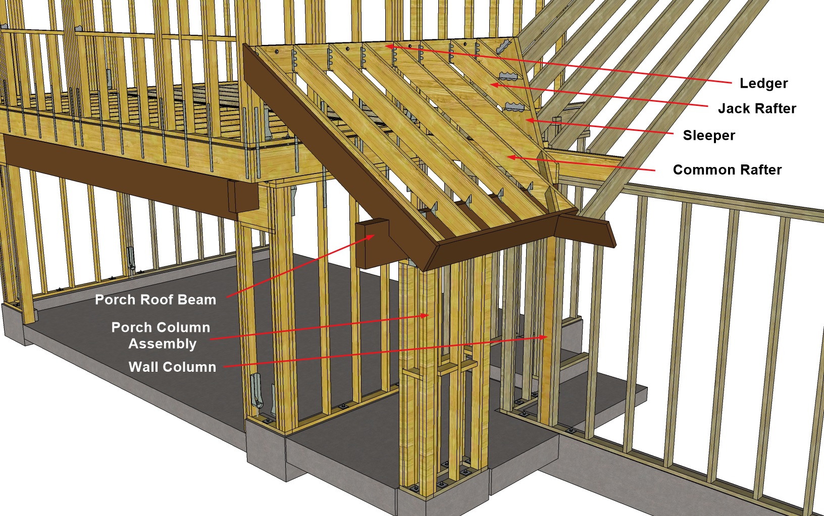
This shows the structure detail of the porch roof.
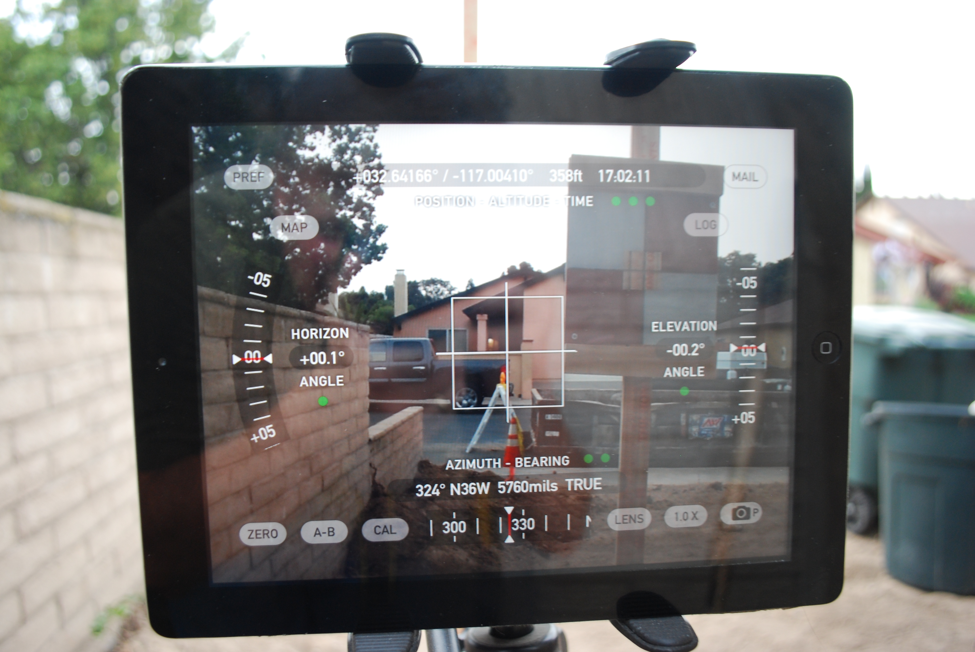
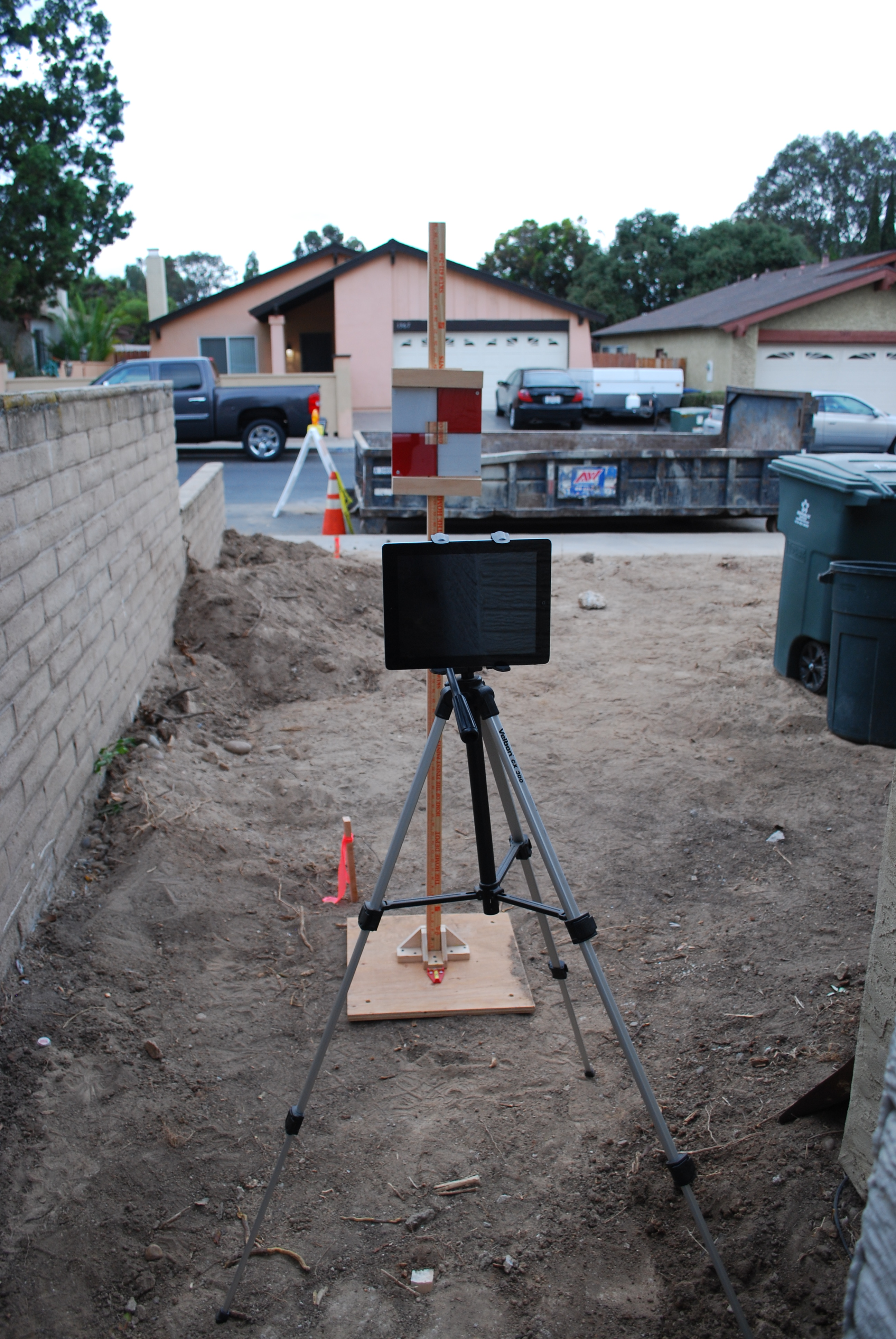
Now that I actually had to start cutting lumber, I was faced with the conundrum of figuring all of those pesky things like lengths, miter angles, and bevel angles. I also knew from past experience that little errors are magnified when you start cutting angles. I did some research on the Internet and I found a REALLY GOOD roof framing website by a master carpenter named Sim Ayers who had a blog entry on EXACTLY what I was trying to accomplish. So I read with enthusiasm and discovered that calculating these lengths and angles directly from trigonometry was pretty tedious. While there are some handy-dandy roof calculators out there, I decided that I already have a “calculator” in with my 3D modeling program. Since I wanted to be as accurate as possible, I used some direct measurements, which are always good when you’re working with existing structures, and then fed them into a simple 3D model and took off the necessary lengths and angles (bevels and miters) from there.

3D model of the porch roof where it joins the main roof. I only took 3 orthogonal measurements (as shown) and constructed the rest of the model from there using the known dimensions of the lumber and the rafter spacing (16″ o.c.).

Close-up of the “sleeper” rafter and how I measured the cut angles. The 3D modeling program gives me the exact angles.
I know this isn’t a really useful “how to” unless you have a 3D modeling program, which I highly recommend anyway, but really, if this is something you’d like to know more about, then visit Sim’s website (link above). Here is the link for his blog post on Off Angle California Framing.

Picture of a “pro” roofing job (by Sim Ayers) using a California sleeper.

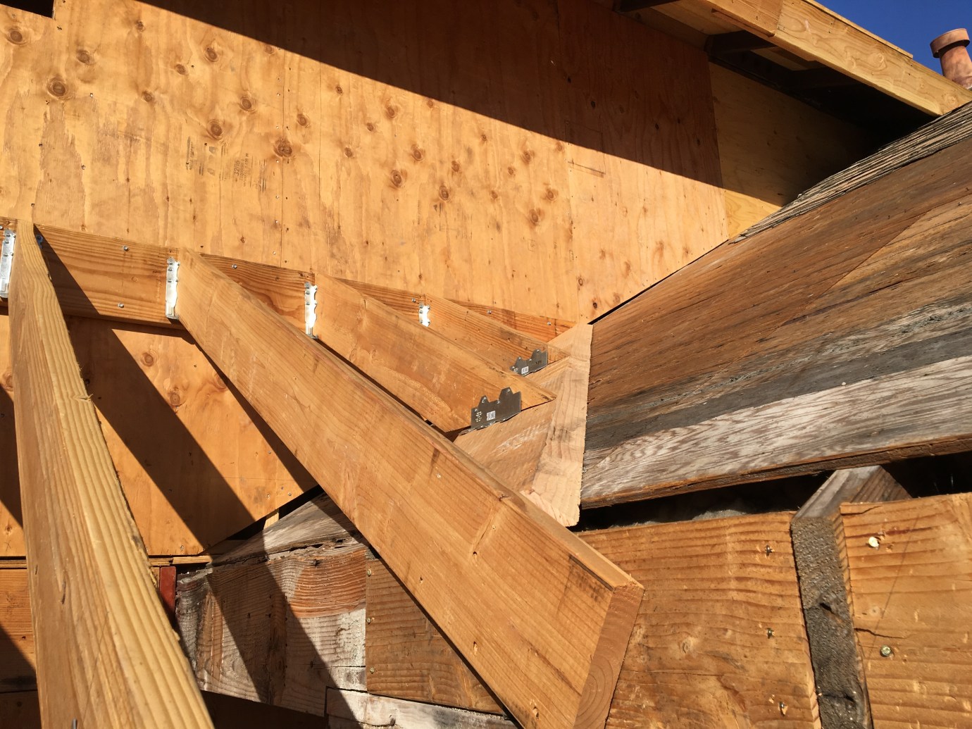
My DIY version. That was some pretty fancy carpentry!
Once I had the rafters and trim in place, I needed to get the roof on. I decided to use shiplap on the entire roof because the underside would be exposed and I wanted a nice look.

Underside of the porch roof matches the shiplap of the eaves.

Front wall extends up to the last common rafter. Note the small space between the main roof, the adjacent wall, and the porch roof. This will be totally closed off when complete. Maybe I’ll cut a small hole in the bedroom wall and use this as a “secret compartment”.

I always sign my work. This area is going to be covered with plywood and stucco. I wanted people 2000 years from now to uncover my hieroglyphics during an archeological dig and argue for decades about what this find meant.
Now, before I got the windows installed, I wanted to load the bedroom with any additional drywall and lumber that I might need because I sure didn’t want to haul it up the stairs! Fortunately, I could rent something called a “material lift” which makes it possible.

Drywall and lumber ready for loading up into the master bedroom. I wanted to get this loaded before I had the windows put in,

I rented a material lift to get all of the plywood and drywall up to the second floor.
Unfortunately, I had some “learning” to do when it came time to actually use it as the following video shows.
Despite my failings, I was able to get the materials loaded and the windows installed.

Drywall and interior lumber loaded into the master bedroom. That was a LOT of WORK!

All buttoned up and ready for the lath folks.,