It’s been awhile since I’ve put in an entry, and there’s really no excuse other than the holidays, a vacation, and not making enough time for it. So, the next few entries will be to catch up a bit and get back into the flow of regular blogging.
Since the last entry, I’ve completed all of the contracting work, and if you look at my bank account, you can tell. Going into this project, I knew that the contract work would be the largest overall expense, especially when you’re talking about new windows, a new roof, re-stucco, exterior paint, and a brand new HVAC system. The HVAC system cost quite a bit, but believe it or not, less than the stucco. Be that as it may, these are simply jobs that a DIY’er cannot accomplish. Either they require a crew, as is the case of the HVAC system or most anything that has to do with stucco or concrete, or is just too tedious and inefficient to do by yourself, such as roofing and exterior painting. Plus, I had enough experience dealing with heights, so that was enough of that.
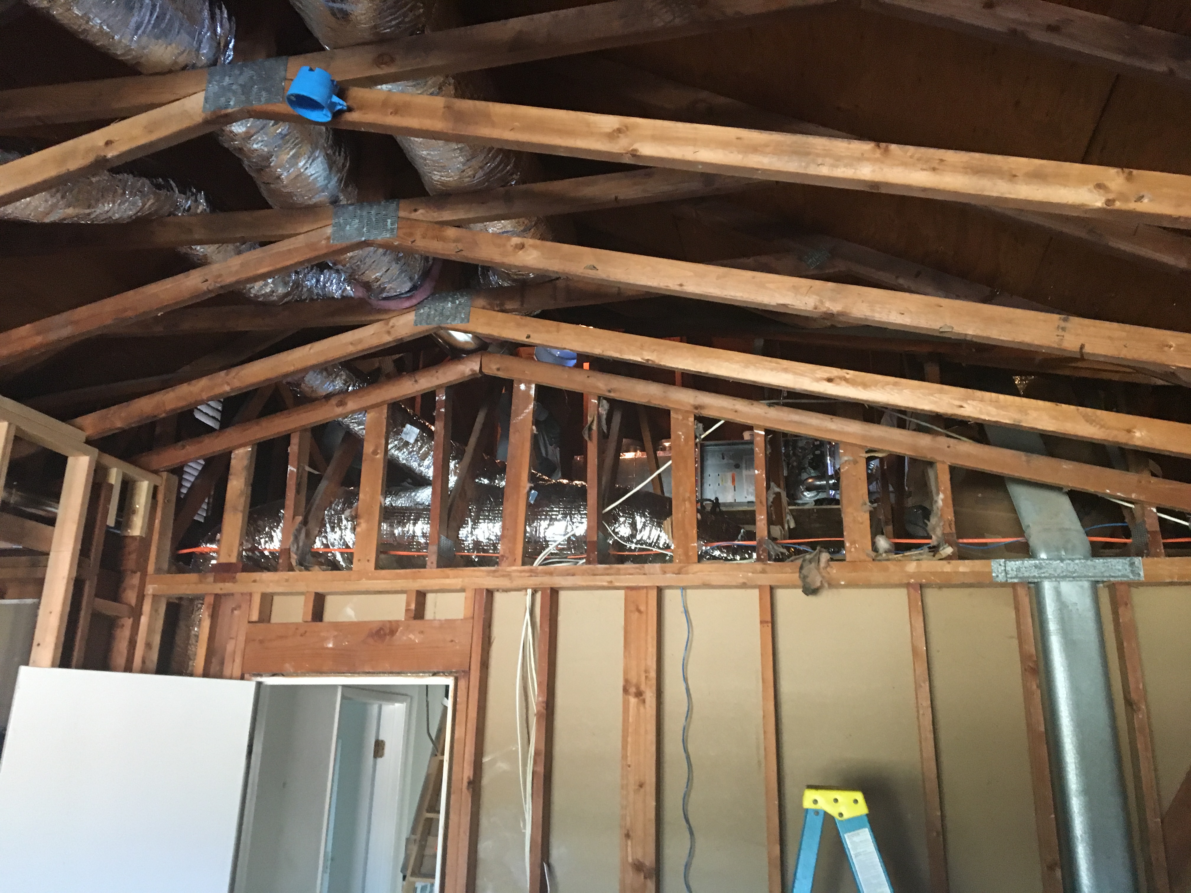
The HVAC installation was fairly smooth. Once I settled on a contractor and a date, they came in, took all of the old stuff out, installed the mechanicals in the attic, and then ran all of the ducting. There are plusses and minuses to putting the HVAC mechanicals in the attic, but for me, the plus of getting the mechanicals out of the garage and simplifying the ductwork outweighed the noise factor (the system is super quiet to begin with) and the minor loss of efficiency by having the mechanicals in a hot attic. I think the fact that I have a cool roof and excellent attic ventilation will significantly reduce that concern.
Here are some pictures:
The new HVAC system involved a lot of ductwork. I ended up with a 3 zone system. Upstairs, downstairs, and MBR. Yes, my MBR is going to be the ultimate retreat and I wanted everything to be the best.
More demolition to make way for the HVAC system. The fun never stops!
HVAC folks working in the attic to put the system in place. The attic is a tough place to work in, so I’m glad they’re doing this instead of me.
The lead installer getting the mechanicals in order. They had to build a support framework in order to place the furnace, air handler, and cooler. Fortunately, the manufacturer (Carrier) makes these units so they can be installed horizontally, which works great in an attic configuration.
One of the HVAC installers, proudly standing by my new condenser. Having A/C put in was a major objective of my remodeling project.
The leftovers of the chimney of the old furnace. Ideally, I would have installed the HVAC system before I had the roof finished, and this would have precluded this extra “stack” but that’s not the way things worked out. Maybe I'[ll get this removed when I do solar (in some future lifetime).
One thing that I had to take care of by myself was to hook in the condensate drain into the house drainage system. Not too big of a deal, but the installer talked me into it, and I didn’t say no. Perhaps it was better because I know I did it right.
SOME of the HVAC system was DIY. In particular, I needed to construct ventilation ducts for my MBATH fan. Since I will have to do that for the other bathrooms, the laundry room, and the kitchen, I decided to invest some time in educating myself in the proper techniques and investing in a few tools to make the job turn our pro.
This shows a special crimper that is used to make a cut-off in ducting into a fitting that can be properly inserted into the next ductwork section.
Here is the MBATH vent going out.
Lastly, the painters came along and finished all of the trim work and exposed woodwork. This really made the place look nice and everything started to look finished from the outside. I got (and still am getting) a lot of positive comments from my neighbors.
Here are some pictures:
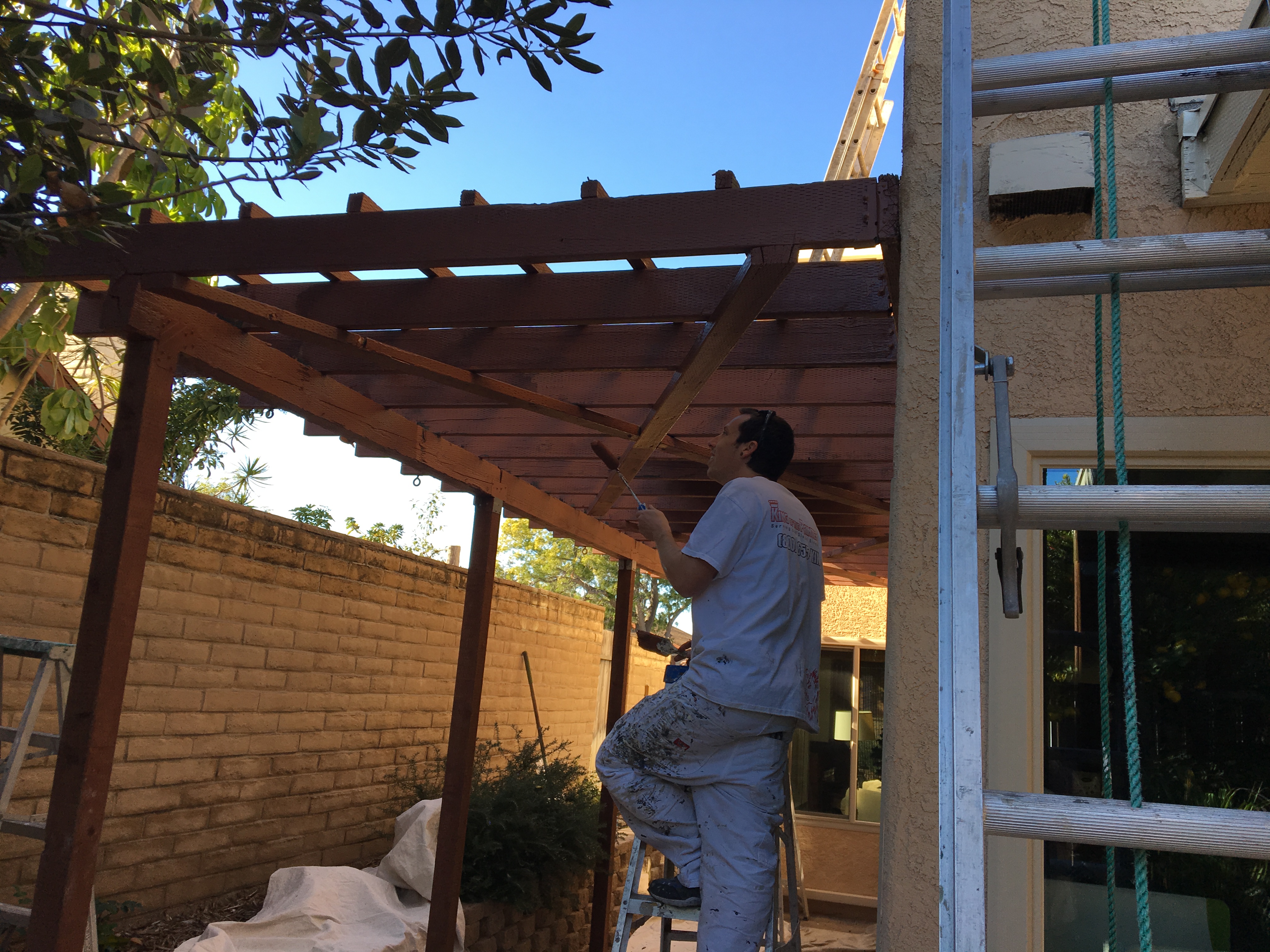
Painter working detail on my trellis. This was very difficult work and he took two days doing it. The results were magnificent!
One of the painters working the detail of the gable vent. Notice how he is up high on a ladder. Better him than me!
I decided to paint a light color underneath the patio cover. This is reminiscent of how porch covers are painted in the South. Bringing in these Southern elements no only pleases Stella, but also lightens up an otherwise dark space. Those Southerners certainly know their onions!
My side yard painted nicely. I had left this unfinished and it really was beginning to look shabby. I knew I needed to paint it, and I’m glad I finally had it done.
The paint match with the stucco is perfect! See how the otherwise gray electric panel now simply melts into the rest of the structure? Same with the gas line. Professional painters are masters at color matching, which is another reason that hiring a professional painter is well worth the expense.
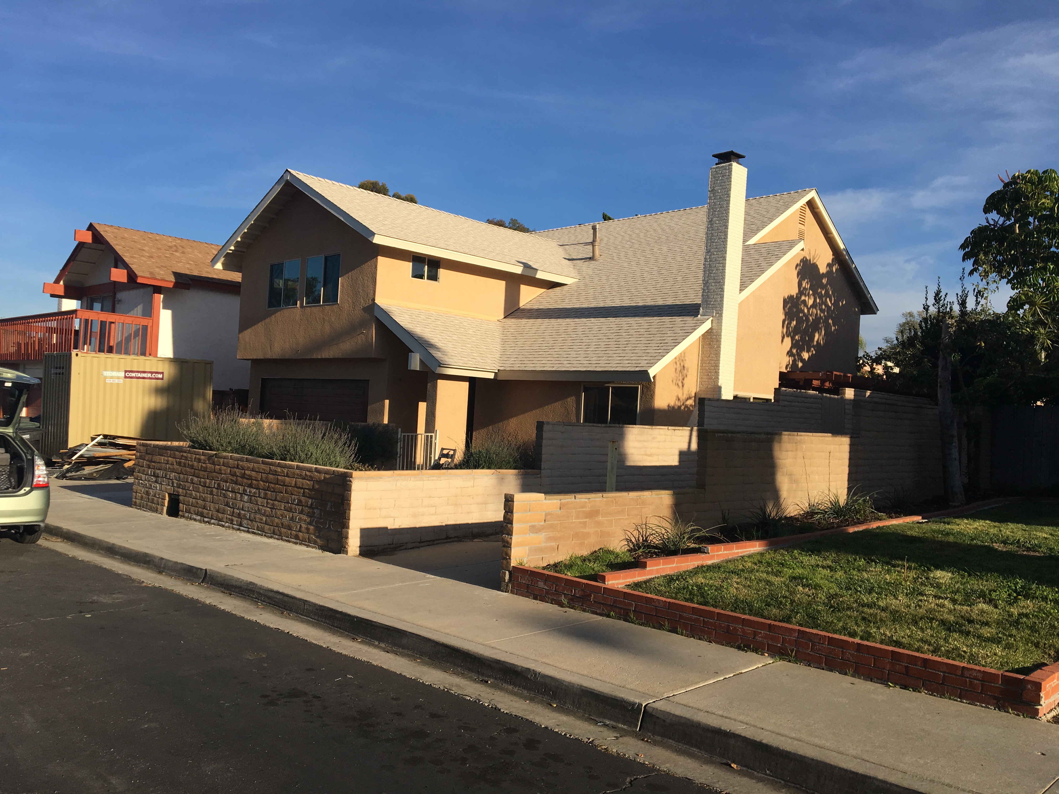
Wonderful picture of the project after painting. This is really looking nice!
In fact, I got a letter from the my homeowners association asking when my storage container was going to be moved. Unfortunately, I had to explain that while the outside of the house looked great, the inside was a total disaster and I had at least another year of work before I was finished.
Since the time the contractor work was complete, I finished off some plumbing and electrical work for the Master Bedroom and got an inspection. I was going to write up some of the details of the electrical and plumbing, but decided to wait until I did another round of it as I have several other rooms to renovate.
With the project sufficiently mature, the time has come to involve other trades for work that I was not going to do by myself. I had to get a new roof put on, get the stucco put up, paint the exterior trim, and get a new HVAC system installed. I had planned all along to contract these jobs out because there really are limits to what even a pro can do by themselves (and I’m just a lowly, but enthusiastic, DIY’er). Finally, I could relax a bit and have someone else do the hard work, right? Well, not so fast….
It turns out that when you start to bring other trades in, you have to work as your own general contractor. That means coordinating schedules, materials, inspections and the like. Fortunately for me, I have a lot of experience in coordinating projects, so this one was really not so tough from a management perspective. However, I had to hustle to make sure that I did my part of the job and get truly ready for the next steps. The one thing that you have to understand are the dependencies that the jobs have on one another.
We start with the stucco. I had to coordinate the stucco and the roofing because, on my home, there was some interrelated work. I had to contract with a roofing company and get on their schedule, and they had to come out and do some preliminary roofing work before the stucco contractor could start. The stucco contractor then had to agree that he could finish the work before the roofing folks came in. But it turns out that some other trades were involved, and because I was covering those, I had to get back to work! For example, I had to finish rough electrical work around the living room and porch because they would be inaccessible after the stucco was up. So I had to DO the work, then schedule an inspection to get it signed off, then finish installing the plywood substrate and all of the other electrical penetrations. I also had to install bases for the new exhaust vents (dryer and ventilation fans) before the lath was put on. Even so, I forgot the doorbell and the intercom penetrations. I’ll just have to compensate later.
Getting ready to cover this area with plywood. I had to tear it all apart to get the porch roof beam installed, and as long as it was uncovered, I took the opportunity to fix up the wiring and add new coaxial and ethernet cabling. I also had to get this inspected and all buttoned up before the stucco lath folks showed up. I had to hustle!
Insulation installed prior to lathing. This is R-19 underneath where the master bedroom floor cantilevers out by about 12 inches.
I also had to install all of the electrical fixtures (see the little yellow wire) and get a new front security door before the lath started. That’s because there was not enough clearance to remove and replace the old door without damaging the stucco. More unexpected work!
So, I finally got to the point where the lathing could take place, but I had one problem: I needed to remove the old electrical panel, and in order to do that I had to get the electrical service transferred. I worked with my stucco guy and we worked out a plan where I would get the electrical service transferred first thing on a Friday, then rip out the old box and have the lather come in and finish the area around the old electric box. Then the inspector would come later in the day. Unfortunately, the guy who was supposed to come to finish the job didn’t show, and the stucco contractor had to get a substitute who (a) came too late, so the inspection was called off and (b) was not a lath specialist, so he missed a few things. Fortunately, my stucco contractor and I came up with a plan “B” and he had somebody come out the following Monday to make sure everything was right, and then we got the lath inspection completed on Tuesday.
Utility workers pulling new electrical cables through the conduit that I installed almost 2 years ago. These guys are working on live lines, but are extremely careful to only work with one at a time. and they know how to do it safely. I’m way to chicken to ever do this.
New meter installed. Actually, it’s really just the existing meter taken out of the old panel and installed in the new main panel. Still, it’s my new electrical work which has been given life!
My old electric meter is now out, but we only have a few hours before the inspector comes to inspect the lath. I’m not feeling good about this…
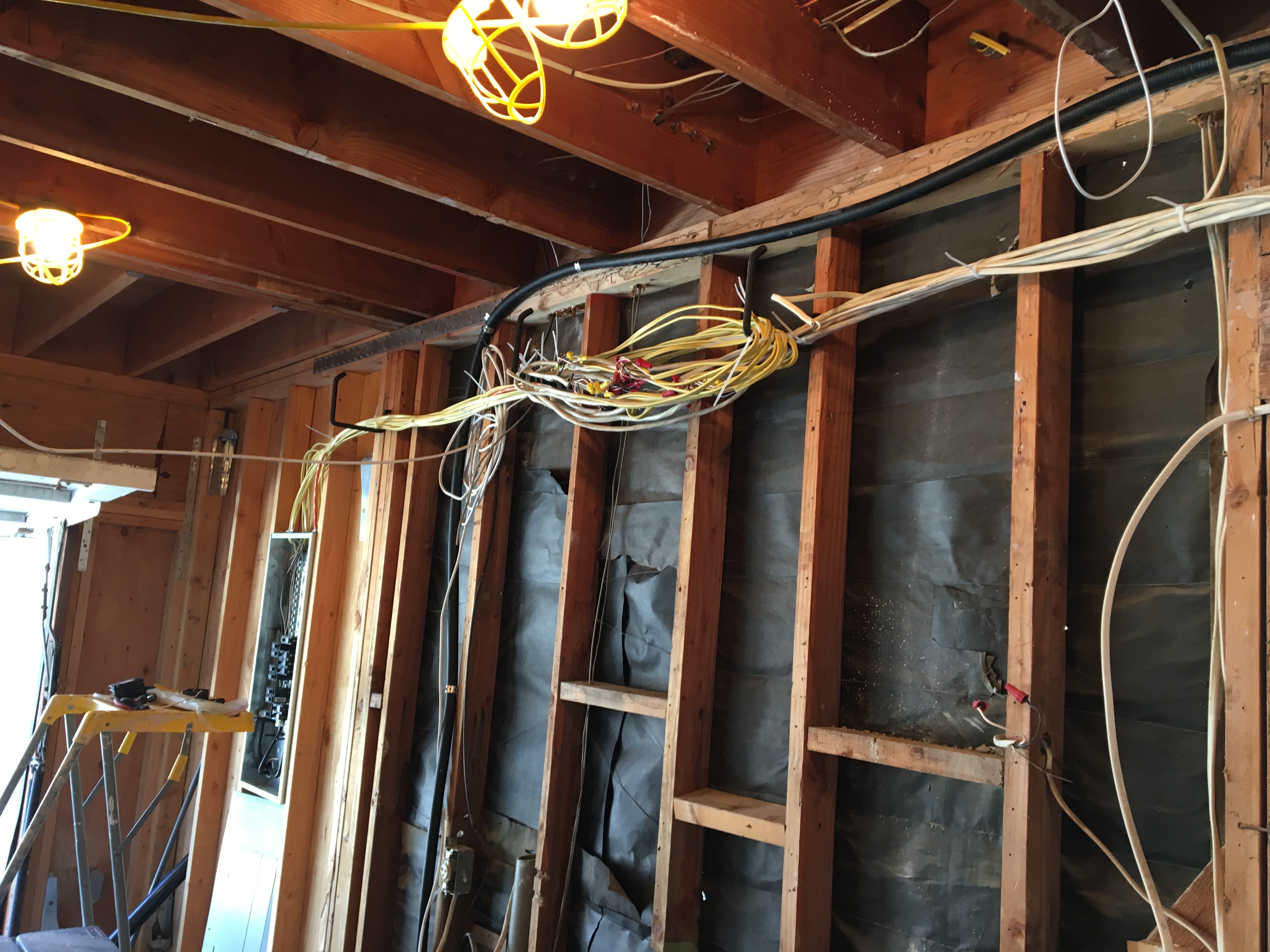
Temporary electrical hookup. I needed to install a working electrical system so I just ran new wires to the existing wiring and secured it. with tie wraps. It’s neat, and it’s exposed so I can monitor it, But definitely will need a total replacement. The good news was that everything worked when I turned it on the first time!
This little experience highlights something that I have found important as a project manager: A good project manager knows how to anticipate problems and avoid them, but also knows how to accommodate when unforeseen problems occur. I knew that scheduling a bunch of things to happen in a certain sequence that Friday had inherent risk. The electrical switchover had to go just right and be timely, the stucco guy had to come early enough and finish, and the inspector had to come late enough to give the lather enough time. So, things didn’t work out, but it was worth the try to maintain schedule. The good news was that I was done with all of the work that I was personally responsible for, so now, I’m not in the way. Nothing makes me more productive than the last minute!
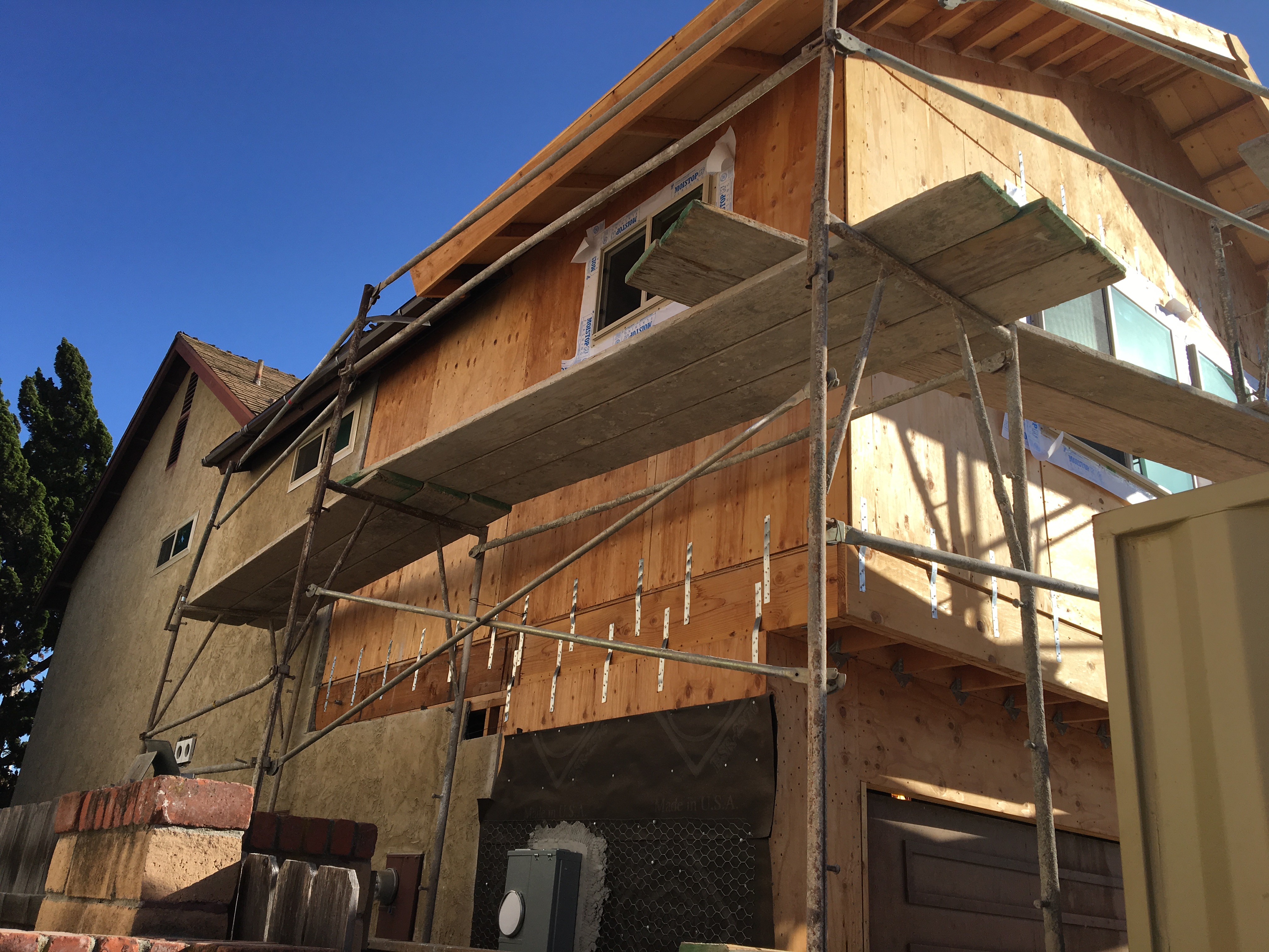
The stucco work commences first with the scaffolding. This Sam the scaffold man. His work is solid and so much better than the tower scaffold that I had to endure working on during the construction of the addition.
Scaffolding all ready to go to start work!
Removing some of the old stucco in front. We just had to get rid of all of that “chunky monkey” look that was popular when these houses were built. It’s not popular anymore.
Lath installed where I will get the new stucco. The rest of the house will be color coated only, but the combined effect will be like getting a brand new stucco finish.
The next day, the stucco guys came in and started the “scratch” coat, which is the first part of a 3 part stucco siding. It is designed to cling to the lath and help tie in the rest of the stucco. It is called the “scratch” coat because the finish is “scratched” to provide a good bond for the rest of the stucco. The following day, they came in and did the “brown” coat. This is the coat that gets close to the final depth of the siding, and is finished fairly smooth. Not sure why it’s called a brown coat, but that’s the lingo. Now it was time to wait a few days before the color coat. I had a hard deadline coming up because I needed the stucco guys out so the roofing guys could come in.
Let the stucco begin! First application of the scratch coat has started.
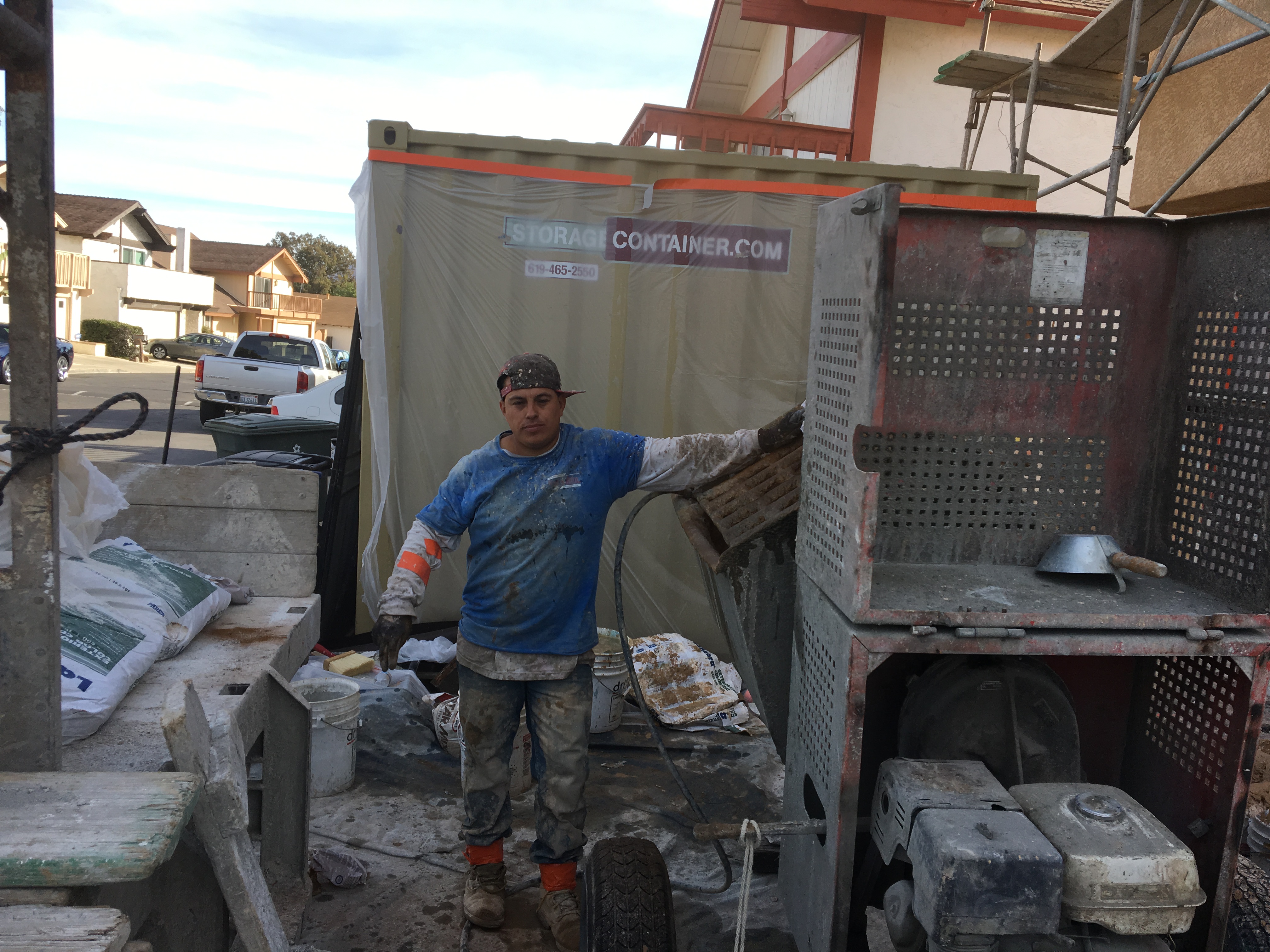
The mixer man dumping a load to hod around. This stuff is really heavy!
Brown coat complete. It really looks good, and will even look better once the finish coat is applied over the whole house.
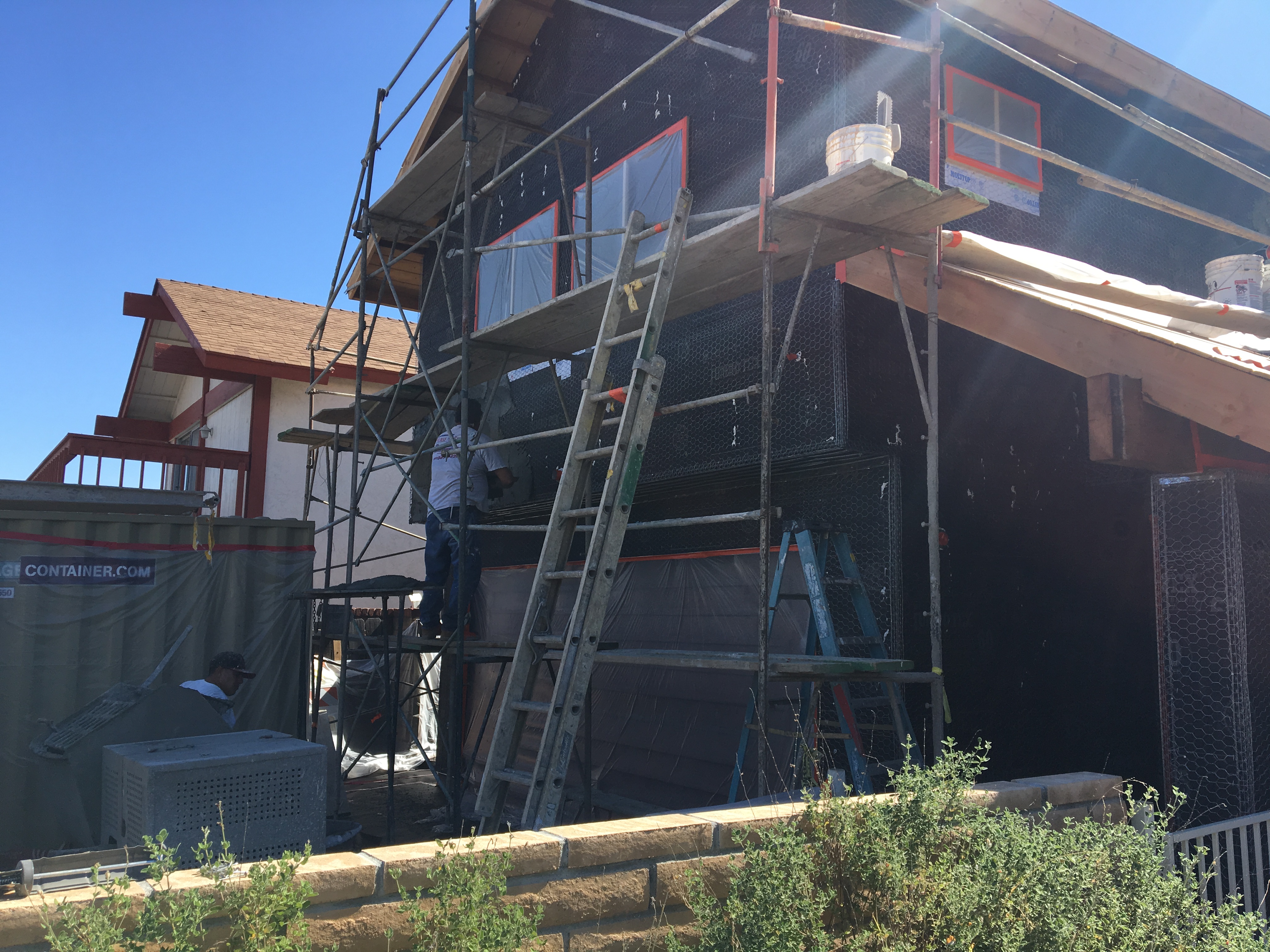
The next week, a couple of guys came out to do the scaffolding on the entire house. That was an all day job and it really had to be all over. This is one of the many reasons that stuccoing an entire house is NOT a DIY project! Then, the stucco finishers came out and started putting the color coat on. When they put it on the back, they smoothed out the existing texture and then put an awesome lace texture on. These guys are really artists — well maybe not Michaelangelo, but same idea (and same medium).
Scaffolding on the West side of the house. Scaffold set-up and take-down is a significant part of the cost of the work.
Scaffolding outside my loft window. I’m glad somebody else is doing this work while dancing on scaffolding!
The man at the mixer mixing the color coat. Apprentices get to do the heavy work of mixing the stuff up and hodding it around to keep the plasterers busy so that they have time to work with the material. This is why I subcontracted this work out. Definitely NOT DIY!
Color coat being applied over existing stucco (right under the eaves).
The master plasterer at work. Michelangelo had nothing on this guy!
Stucco is a very messy trade. Sort of like sausage making — you don’t want to see the process, but you like the result.
In the end it all worked out. I was very pleased with the result, and my home is becoming the envy of the neighborhood. Next, onto the roof!
Close-up of the texture. This is real artisan stuff here. I have a very unique product that looks great!
Color coat complete. Looks fabulous! The roofers are coming next week, so the scaffolding still has to be removed. It’s going to be tight with the schedule!
OK sports fans! This moment has been many years in the making. The moment when I, and only I, will bust out the structure of our house with the intention of EXPANDING our living space and making a fantastic en-suite (master bedroom-master bathroom) in a manner that puts HGTV to shame! Because this is a big task, and I needed to focus all of my spare time on it, I haven’t made a blog entry for a while. It’s either work on the house and generate material for the blog, or write the blog and make stuff up. I prefer the former. I took 2 weeks of vacation to accomplish this bodacious task, and I got most of the way through. At least I put up the walls and the roof trusses. But it took another 4 weeks of my spare time to finish the roof structure, put the trim on, and finally cover the roof.
Phase 1: Demolition.
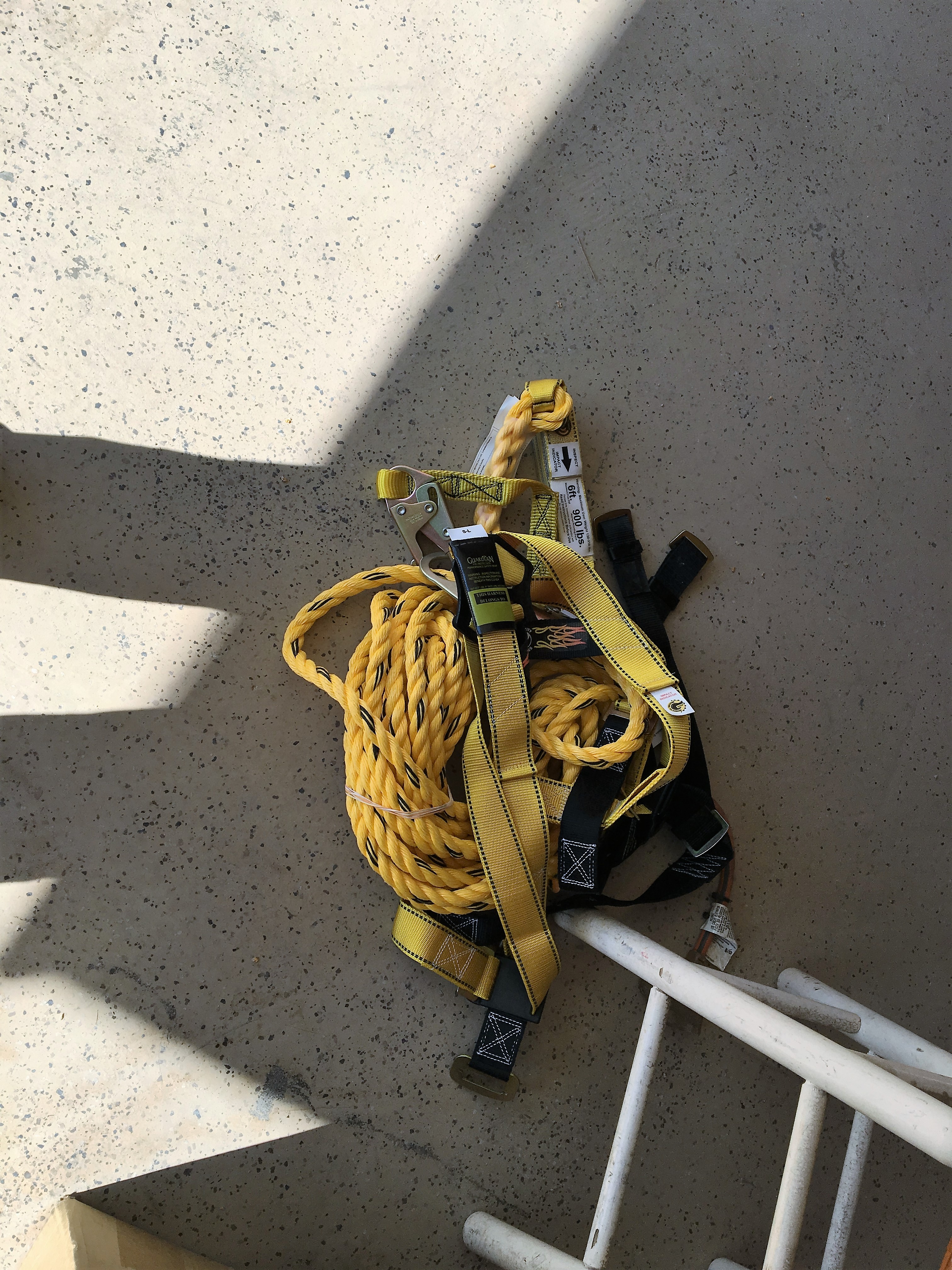
As with most building projects, the first part is the demolition. I know I’ve been talking about demolition a lot, so I won’t bore you with too much more of it. As with most demolition projects, the best course of action is to work from the top down, and to disassemble whatever you’re demolishing in the opposite order that it was built. Because the bedroom extension will also result in extending the roof (sleeping under the stars is OK if you’re camping), I began by stripping the shingles from a portion of the roof. My biggest concern was roof safety. If there is anything dangerous in this endeavour, this is it. So I took some time to get the proper equipment: roof jacks, scaffolding, and a safety line with a harness. Yes, it cost a few bucks, but it’s cheap insurance. As I have mentioned in previous posts, I’m a bit obsessed with safety. The other nifty tool that I got was a roofing shovel. This tool has a notched spade that you ram underneath the shingles to get under the roofing nails, and a fulcrum that allows you to pop the nails right out. The technique is to start at the top of the roof, and after you pry off the ridge shingles, you get a start on the shingles at the top and then just go to town. That being said, even with the right tools and safety equipment, it’s hard, tedious, and somewhat messy work.
Safety harness and safety line. It’s kind of a PITA to work with, but it sure provided me peace of mind. This is what all the pros use now.
Roof safety: Roof jacks to provide a solid base for working.
Roof stripping complete. Took me all day.
Next was the trim. One might think that removing trim is no big deal. But it was to me because I had to get way up high and had to bang and lever stuff around, keep my balance while precariously perched on the scaffolding and ladder, all the while making sure that whatever fell down didn’t fall on me. The other bad news was that we were experiencing a record heat wave, so that meant that every push and pull was accompanied by beads of sweat in my eyes, lack of energy, and dehydration. I kept trying to drink as much water as I could, but there’s really no way to keep adequately hydrated while doing heavy physical labor in 96 degree heat.
Roof overhang and trim removed.
Now, on to the messy part: Knocking down the walls. This part of the demolition worried me a bit. I didn’t want to spend a lot of time cutting stucco vertically on the wall, but I needed to get the wall down in pieces that were not so big they would damage the subfloor when they would inevitably come crashing down. I first had to knock down the gable wall, first by taking down the triangular portion of the gable by splitting it at the top plate, and then taking down the vertical walls. Since the side walls are load bearing, I had to build a temporary structure to accept the load. Also, I only took down one of the side walls at a time so only one side of the roof was unsupported. Because I didn’t want to have to cut stucco while precariously balanced on a ladder from the outside, I decided to pull the wall down from the inside. Since I know that the easiest way to cut the stucco is when the stucco is lying flat, I decided to yank the whole wall down and then disassemble it. Sure enough, with all of that weight of the stucco, it came down with a big crash! This turned out to be a very bad thing because I, like a dummy, did not think to put temporary bracing under the joists of the bedroom floor. Here is the result:
Gable wall demo complete. What have I gotten myself into?
Temporary bracing to transfer the roof load to the floor. Too bad I didn’t complete the job by constructing concurrent bracing to properly transfer the load from the underlying joists to the slab foundation below.
Wall before demo.
Wall after demo.
Minor damage from the downfall of stucco. I had a surprise coming.
Joist failure as a result of not properly transferring the load to the foundation. I’m going to put a bag over my head when I call my engineer for recommendations.
Cracked joists. I needed to deal with termite damage anyway, so really no extra work. But I sure feel dumb!
Phase 2: Build the walls.
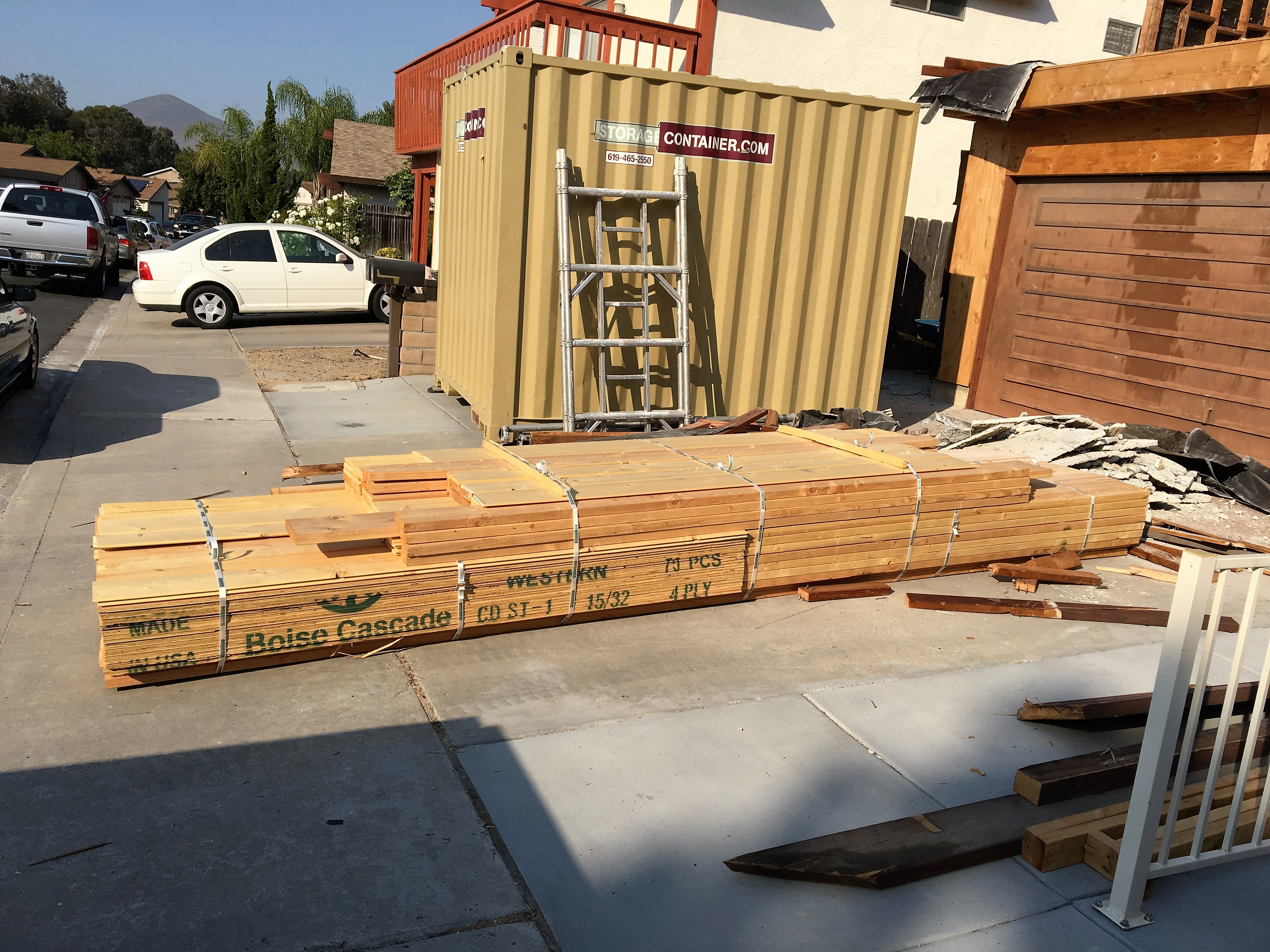
One of the tricky things about building on a second floor is that you actually have to get the building materials UP to the second floor. This meant spending the better part of a day tediously pushing lumber, mostly one piece at a time, up a ladder and onto the second floor. I had to plan ahead to make sure that I had all of the lumber for the entire build, including the interior framing and plywood, because I did NOT want to struggle hauling this stuff up the indoor stairs after I closed in.
Lumber delivered. Now, to get it up to the 2nd floor!
Building a standard wall for a house is pretty straightforward. You layout and cut the lumber, build and sheath the wall while flat on the floor, and then raise it up. The easiest way is to start by carefully aligning your sole and top plates, and then doing the layout of the studs all at once. This not only saves time, but more importantly, helps to make the wall square because all of the top and bottom measurements are the same. The next thing to do is to make a “kit” for all of the framing lumber. This not only includes all of the studs, but also the headers, sills, cripple, and jack studs for the window and door openings, as well as the framing for each corner. From there, it’s a simple matter of separating the sole and top plates, scattering in the pre-cut parts, and then methodically nailing them together. It’s important to follow a nailing schedule, meaning that the prescriptive codes require specific sizes and spacing of nails for a given assembly. For example, a stud to sole plate or top plate can be two 16d nails driven longitudinally into the stud (“face nail”) or three 10d nails driven in from an angle (“toe nail”). Fortunately, the County of San Diego has a convenient summary sheet of all of these requirements, which the plans inspector “suggested” that I include as part of my building plans. I took the hint.
Wall lumber cut to length and organized to form a “kit”. I did this for the lumber for all three walls.
All kit parts need to be labeled so you don’t get confused. These are labeled “C/O” for “cripple” stud (window), and “outside” because the top is cut at a 5º angle to allow for water drainage from the sill.
The next thing to do is to sheath the wall. In many building situations, it’s better to put the wall sheathing on after the walls are raised because you can do some adjustments for dialing in plumb and square, and you can apply the sheathing in a fashion that overlaps the structural assemblies to add some strength. However, it’s more difficult to fool around with large pieces of sheathing, particularly plywood, when you’re trying to hang it vertically. Putting the plywood on the walls while they were still on the floor was a no-brainer for me as a one-man-show. One thing I learned about walls is that 2×4 lumber can be pretty flexible on this scale. You have to use a big sledge hammer to bang stuff around, but it’s important to square things up before you put the plywood on, because once the plywood is attached, it ain’t movin’!
Lastly the wall needs to be raised. There are lots of pictures of construction crews all gathering around a wall, and with a mighty “heave ho”, the wall comes up. Not possible with just me doing the heaving. Fortunately, there is an outfit (Qualcraft) that makes something called a wall jack. This operates much like the old-fashioned car jack that you used to hook under your bumper to change a tire. But instead of a metal jack shaft with teeth, it uses a long 2×4 piece of lumber. It’s pretty ingenious, and here is a short video and some pictures:
Wall jacks in position, ready for action!
Close-up of wall jack. 2×4 screwed into the floor prevents kick-out.
Last wall up, ready for trusses.
Phase 3: Place the trusses.
Now that the walls were up, it was time to get some help. The trusses, by themselves, are not particularly heavy, but they are difficult to handle and are fragile if they are handled while they are flat. Fortunately, the same co-workers that helped me place the big beam I needed for my garage portal were willing to spend a morning yanking these bad boys up and securing them into position. I only had 4 of these, but we had a little trial and error at first, so it took a little longer. I also had them come back to help me with the gable wall. Now, it was up to me to finish detailing the front of the roof line with outlookers and blocking.
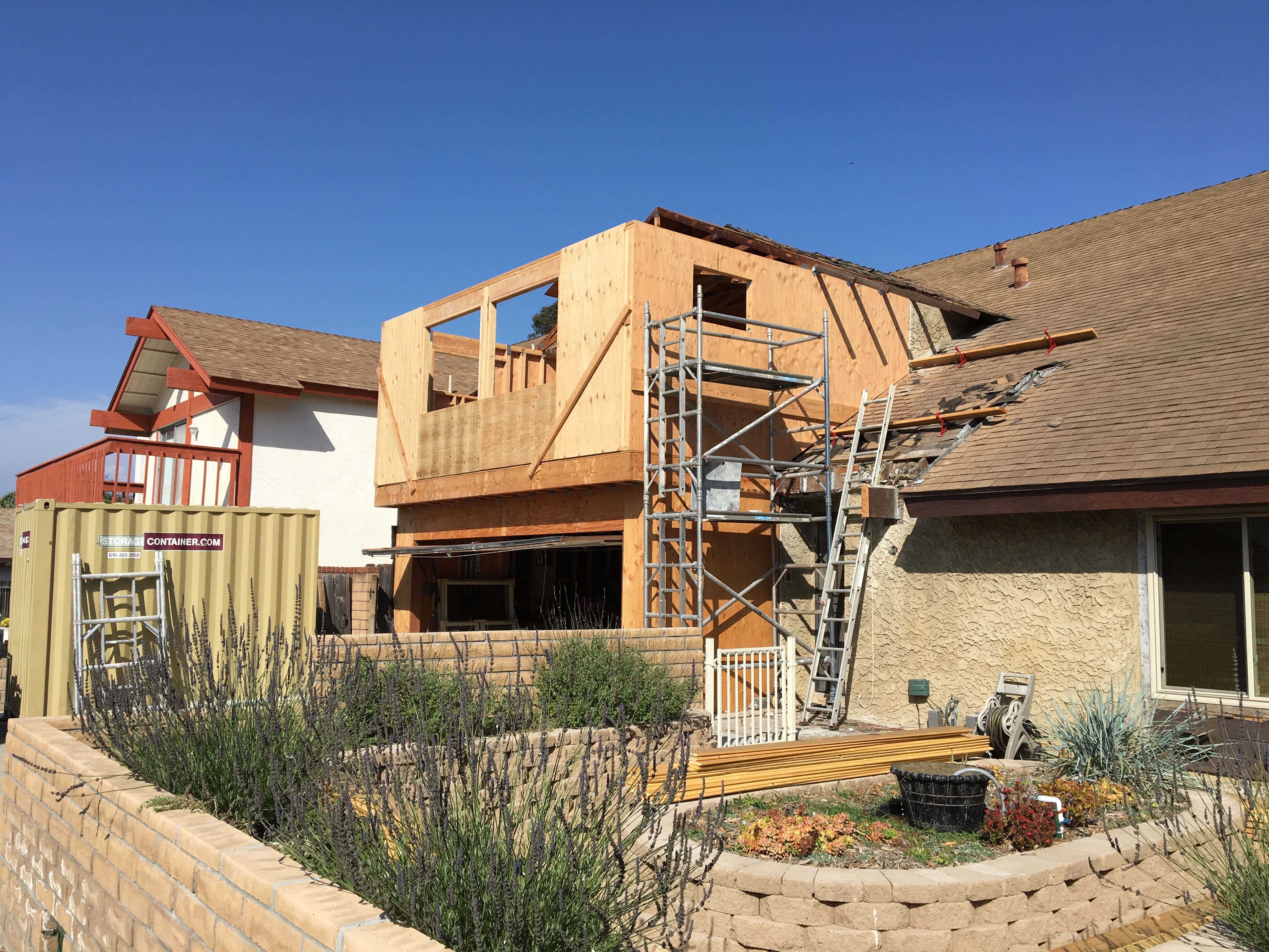
Last wall up. Things are beginning to take shape.
Trusses delivered, ready for installation.
My “crew”. Their help was indispensable in completing this phase of the project.
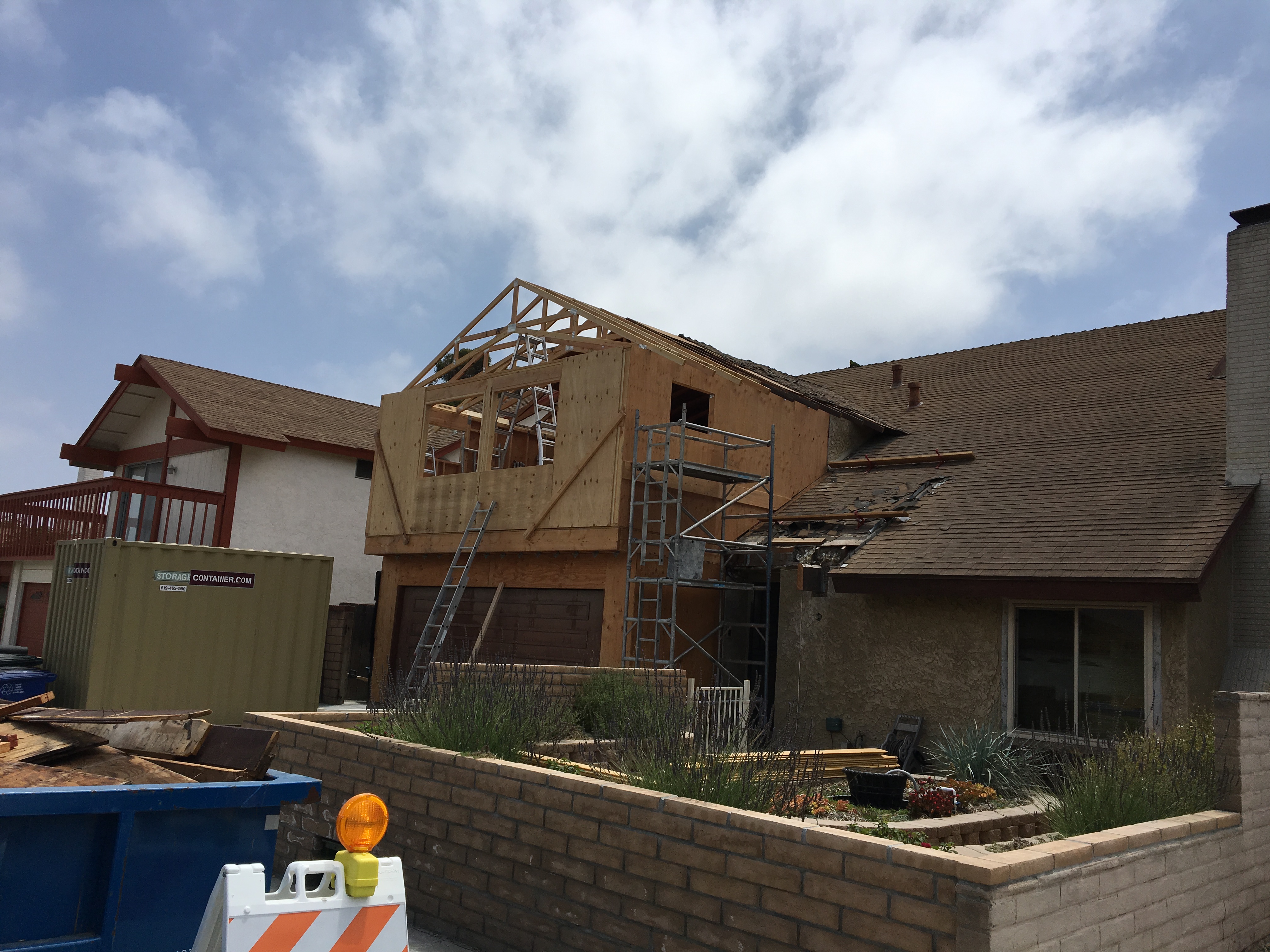
Trusses are up!
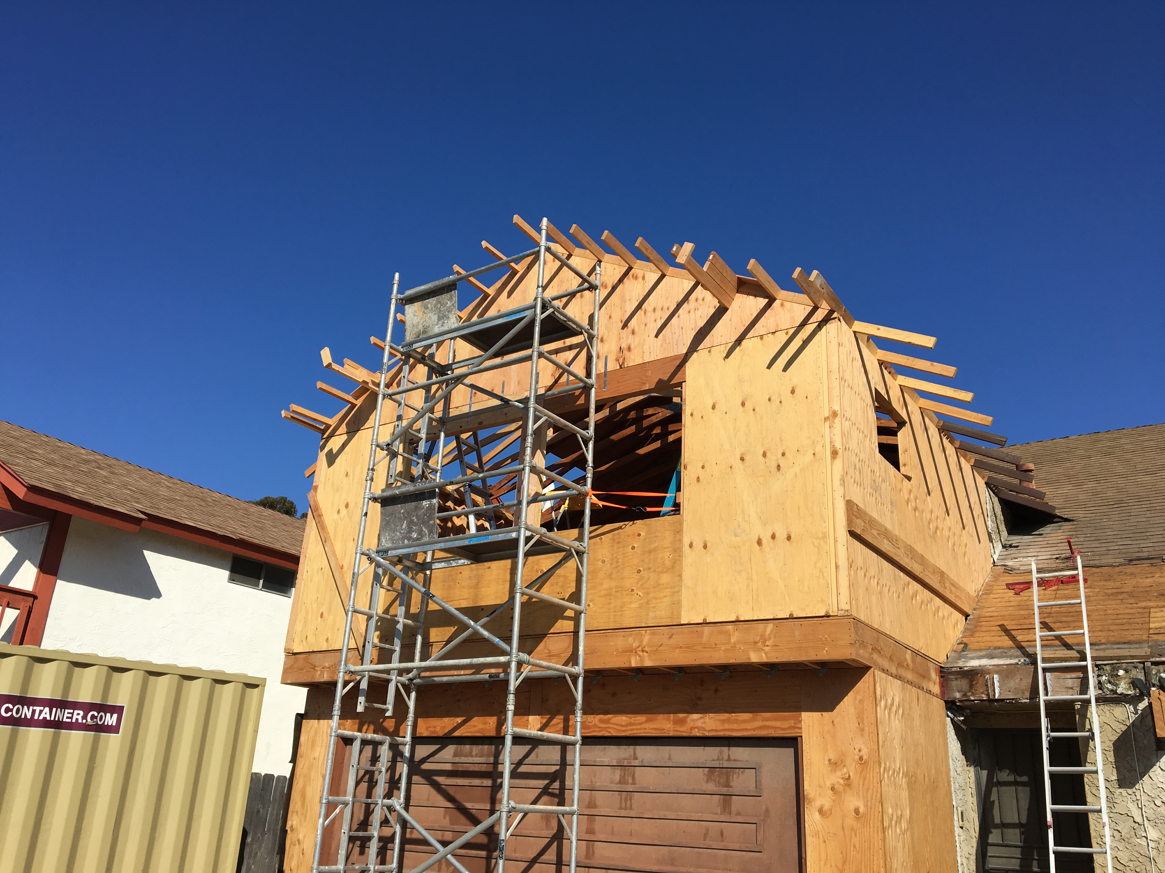
Gable wall and outlookers in place.
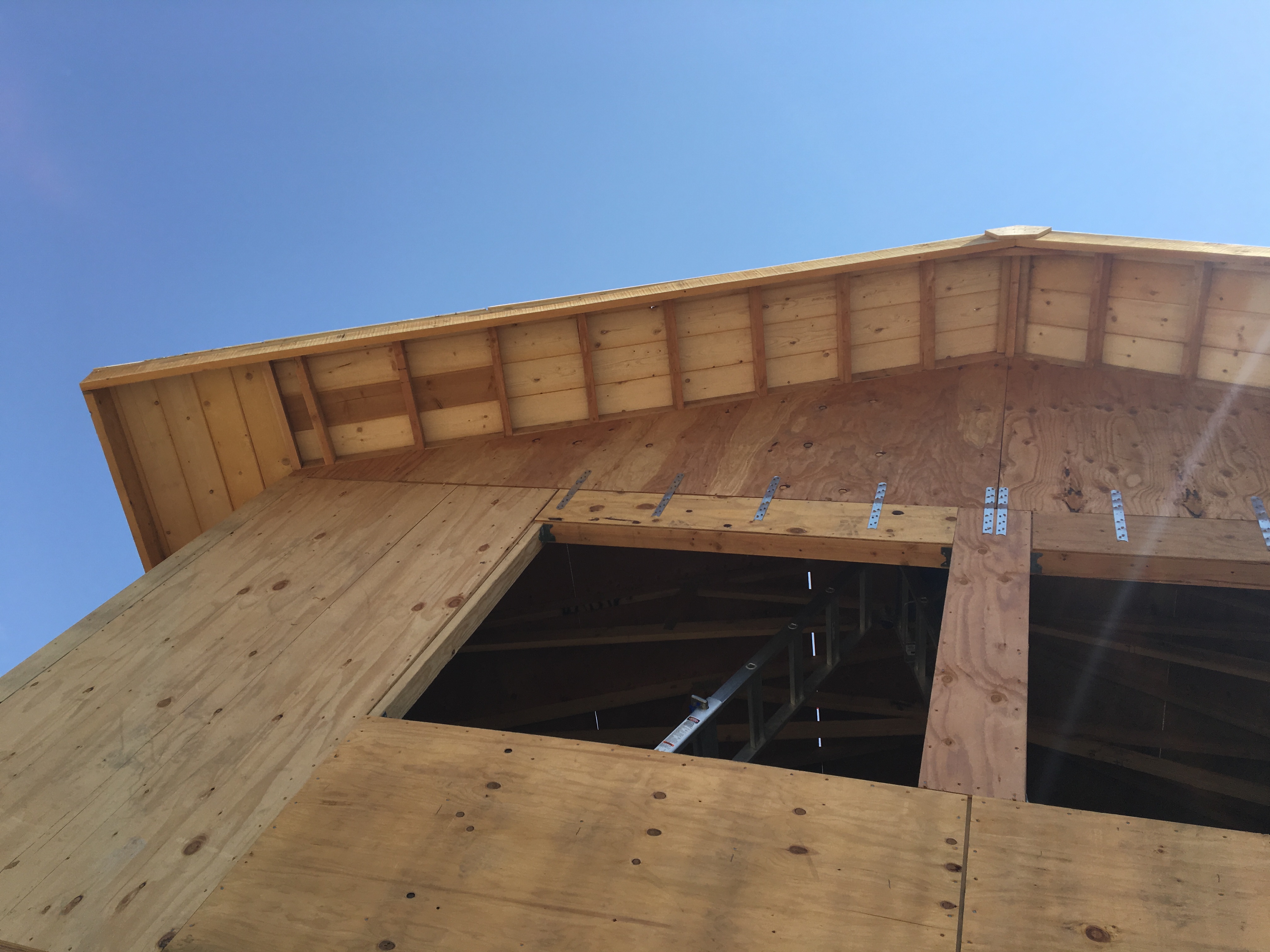
Phase 4: Finish the roof.
Finishing the roof was actually a two step process. I first needed to get the trim boards placed on the ends of the truss overhangs and outlookers. These are called “barge” rafters, and these were particularly long and heavy. I spent an entire day messing around with scaffolding and engineering a “third hand” to hold the rafter while I put it in place. But when I found it impossible to even the the board up there by myself, I knew it was time to call my crew back for another session. Sure enough, in about 3 hours, we were all done. Finally, I was able to get the roof sheathing in place. If this were a flat surface, this job should have taken about 3 hours. But because it was on a roof, I had to laboriously move around and reconfigure scaffolding, haul materials up and install them, and then move onto the next part. Getting the plywood up for the roof sheathing was also challenging. I decided to make a simple lifting fixture from scrap 2x4s that I screwed onto the plywood, and then used a rope to pull up the plywood. I also set up a couple of long boards to help the plywood slide up to the roof. This lifting fixture also proved valuable in placing the plywood because it gave me some leverage. Note that I had to place on piece of plywood at a time using this method, so, again it took a long time.
Another thing I learned about working on a roof is that it’s physically hard! That’s because you constantly have to fight against gravity because you’re working on a slope. Plus, there’s no shade (duh!). So, in addition to it being hot, all of that up-and-down and muscling the plywood in place really wore me out. In the end it took about a week (!) to finish the roof. But I liked the result.
Outlookers in place, ready for the barge rafters. Note the “3rd hands” to the right and left of the scaffolding on the outlookers.
Barge rafters in place. Beginning to look like a house!
Shiplap appearance boards are on the roof overhangs to match the rest of the house.
Roof all done! Looks nice.
The inside. This is going to be a nice bedroom!
The proud builder and his creation.
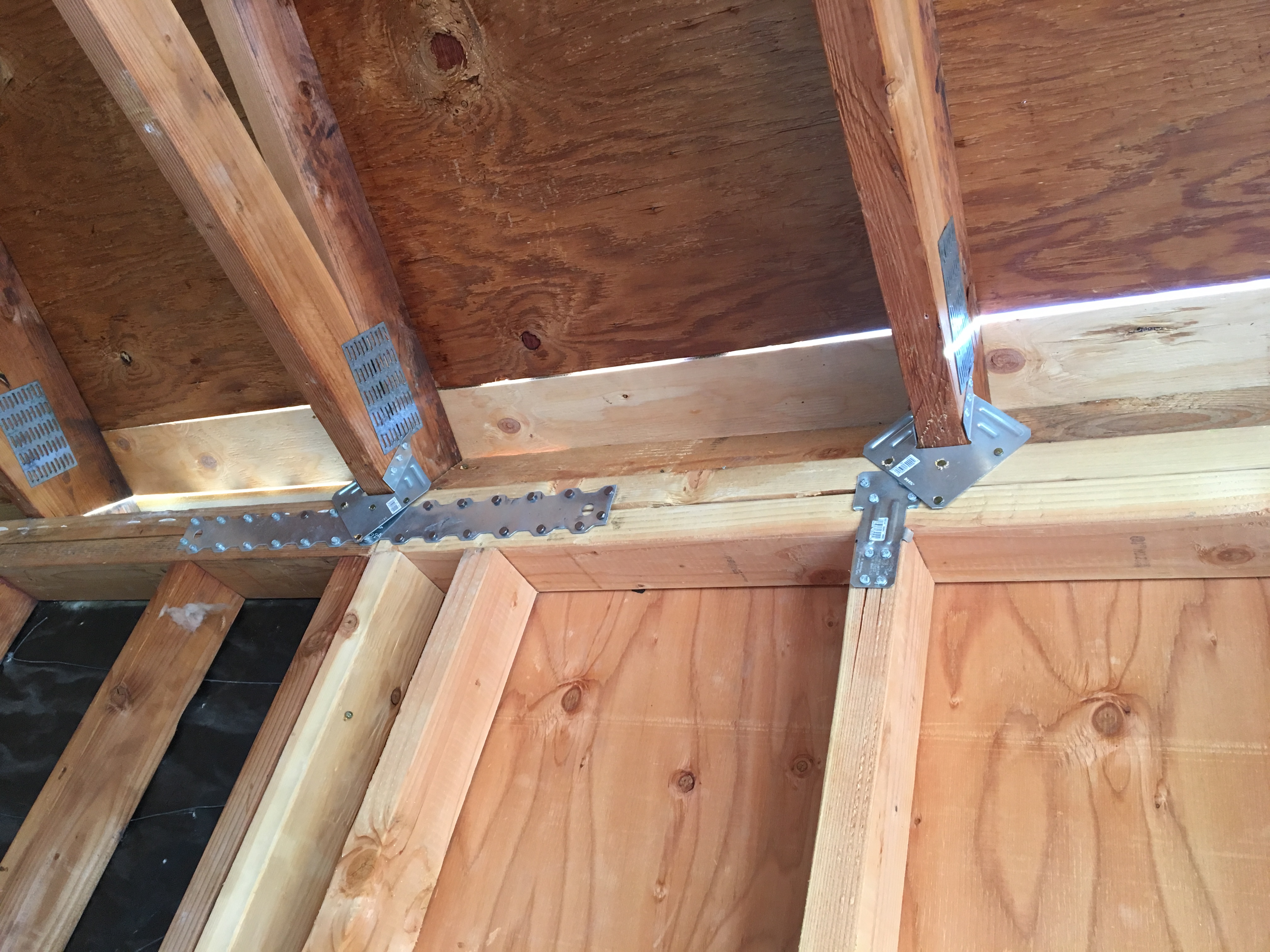
Phase 5: Install the connectors.
Actually, installing the connectors is something that I did as I went, but I wanted to highlight the fact that the days are gone when you can simply use nails to build a house. Modern house construction uses metal connectors almost everywhere, especially between major components (e.g., foundation to first floor, first floor to second floor, second floor to roof). There are hundreds of connectors to choose from, but that was taken care of during the design phase, so the ones that I’m using are all in my plans. Each connector has a specific fastening schedule (number and type of fasteners), so you have to be pretty meticulous. I made copies of the specification sheets for each connector that I used, and highlighted each one and keep them in my permit book so that when the inspector comes by, I can show him what I’m working to. I really did learn something when I prepared for my inspections in the Navy!
Metal connectors for the roof, studs, and top plate.
Connectors between gable and front wall. I still need to add connectors between the wall and the rim joist on the bottom.
I’m hoping the pace will now pick up with the roof, windows, stucco, and HVAC contractors coming in. Stay tuned!
Let’s face it: I’m a dedicated cat lover. I didn’t used to be, but when I was first dating my yet to be wife, she had mentioned that she liked cats and had many a fond memory of them. My tiny little pea-brain thought: “Well, wouldn’t it be nice to get her a cat because she likes them so much.” She did like the cat, but it came with the newfound responsibility of being a “cat-daddy”. It was all good, though. She showed me how to relate to them, and that they were very affectionate, but their life was lived on their terms, and after a fashion, I came to respect that. Since then, we’ve had many a cat, and I now believe that those who don’t like cats, don’t know cats.
Cats have always come into our lives either through the local shelter, or have just shown up. We never pass up the opportunity to attract a stray and needy cat, and, if it is not obvious that the stray is neutered, we get it to the vet (trapping it with a live trap if necessary) and take care of that little piece of business. We started with the one cat way back when, but as Earnest Hemingway says: “One cat just leads to another.” so we’re at four (at the moment).
A couple of things that cats need are (a) territory they can claim and (b) places for their territory that are interesting to them where they can perch, play, sleep, and watch. For indoor cats, this can present a challenge, especially if you have more than one cat. The answer is to “catify” your house. There are lots of good ideas out on the Internet about “catification”, and these primarily emphasize making use of vertical spaces, such as shelving, steps, climbing posts, and perches that allow the cats to move around and find more space. However, all cats like to be outdoors. The conundrum is that outdoors can be dangerous to cats because they can become prey to other animals (like coyotes) and can become injured by other cats, cars, and mean people. But, what if you were able to put them in a big cage? And what if that cage shared a wall with your home so that they could have a private “kitty door” they could use at their whim? And what if you made that cage big enough for people to have a couple of nice outdoor chairs and a small table so you could enjoy the outdoors with the company of your cats? Say hello to the “catio”.
A catio is a patio that has been modified to accommodate the needs of cats that keeps them safe while they enjoy the pleasures of the outdoors. Some are very small — basically a shelf extending from a window with a cage around it. Very popular in cities. But for a home that already has a patio with a patio cover, as it is in my case, it is a simple matter to add some rudimentary framing, a couple of doors (one cat, one human), and some wire mesh, to have a nicely defined outdoor space that can be enjoyed by the whole family. Yes, cats are part of the family. But, to really bring it up to proper “cat standards”, one needs to add some cat specific architectural details that give the cats places to hide, peek, perch, watch, climb, run around, and sleep. These don’t necessarily have to be complicated, so I decided to have some fun in designing the interior of the catio to provide the cats interesting and fun things for them to do, while still maintaining a sense of style. Here are some pictures of the design.
Here is a rendering of the catio with the cat “toys”. There are numerous features that are attractive to cats, such as vertical interest, views outside, places to run, hide, and peek, and places to climb and scratch.
The actual building of the structure is pretty simple. I used basic 2x dimensional lumber for framing everything out, and decided to use deck screws to put everything together. Because none of this is load bearing, and was built against the existing framework of the patio cover roof and posts, I didn’t need a permit. Having said that, I did use my SketchUp modeling program to do a detailed design because (a) it helps me visualize the final product, (b) helps me figure out how I’m going to build it, (c) helps me with the material estimates. I put some effort into the door because it has to be sturdier than a typical screen door, and if you’re using dimensional lumber that is pressure treated, it probably won’t stay square because it is sold as green (wet) lumber and will warp when it dries. I found out this the hard way with my first attempt at a catio. This time around I used kiln dried 2×6 lumber for the door and joined it with mortise and tenons, held together with waterproof glue and dowels. Here are some pictures of the final design.
Catio Framing
Catio Toys
Detail views of the construction.
And of the construction.
The “before” picture. All tools in place and materials staged (on the left). Time to start framing!
The framing is done! I paid particular attention to the frame for the door, making sure that it was square and plumb.
Framing is spaced at 36″ to fit the 36″ wide roll of wire mesh (with overlap). This minimizes the time cutting the mesh.
After the framing was up, I installed all of the “cat toys” and the door, and then took them all apart for painting. The plywood and untreated wood needs protection against the elements, and it’s easier to paint these parts while they are flat, and disassembled. They all go back together pretty fast!
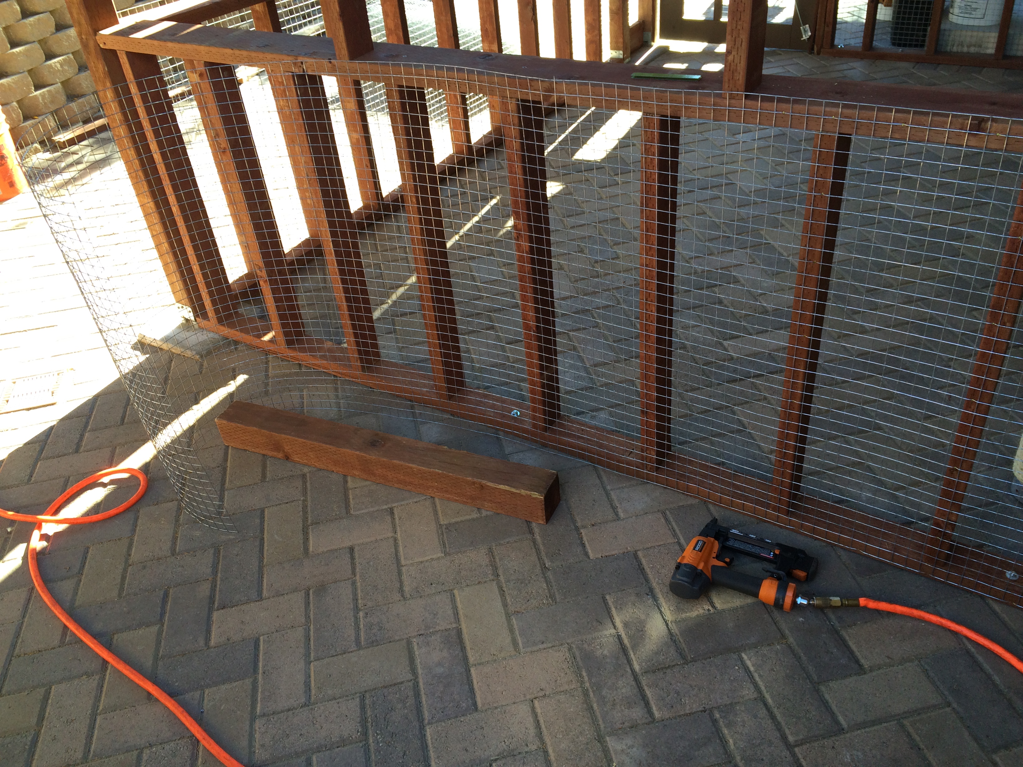
The last part is covering the structure with wire mesh. I used a 1″x 1″ 14 ga galvanized mesh that is available from Home Depot if you special order it. The first time I bought this stuff several years ago, I paid about $100 in shipping because the stuff was not available locally. What I found out was that if you find the product you want from a manufacturer that does business with Home Depot, you go to their “pro” desk and ask them to special order it. No shipping charge!
I found the 1″ x 1″ mesh to be ideal because (a) it looks nice (chicken wire makes it look like a chicken coop — not my decor), (b) it’s sturdy enough so the cats can climb on it and not deform or make holes in it, and (c) it’s large enough to minimize the obstruction of the view from inside, yet small enough to prevent unwanted “visitors”. The visitors that are small enough to get through are taken care of by the cats….
I chose a 36″ mesh width because that fit very well with the proportions of the framing, which minimizes the amount of cutting of the mesh. It also makes it easier to handle when attaching to the framing.
Attaching the mesh single-handedly can be challenging because the mesh has a “memory” that tends to spring the damn stuff back on top of you and give you scratches. When people see my recent scratches, they ask if they are because of my cats. Well, in a sense, yes. But I digress. I found that laying a long piece of 2x lumber lengthwise will (a) prevent the roll from coming back on you when you’re cutting it, and (b) can help you stabilize the piece when you fit it to the frame. The other “must-have” is a pneumatic stapling gun. It makes aligning the mesh fairly straightforward, and for quick work in stapling it down the rest of the way. Yet another reason to buy that “new tool”. At least one new tool per project…. that’s my motto.
Using a spare 2×4 to hold the roll of wire mesh in place for measuring and cutting.
The mesh has a “memory” which tends to roll it back to its original shape. If you try to straighten it out, chances are it will be deformed when you staple it in place. The best strategy is to work with the spring-back. Align to the framing by tacking the middle of one end to the framing, and then aligning one edge to the framing and tacking the edge in place. Once aligned, it is relatively easy to “unroll” the mesh as you progressively staple it to the frame.
The 4×4 is being used to hold back the “spring” in the mesh. Once the mesh is aligned, it is easy to tack in place with the pneumatic staple gun.
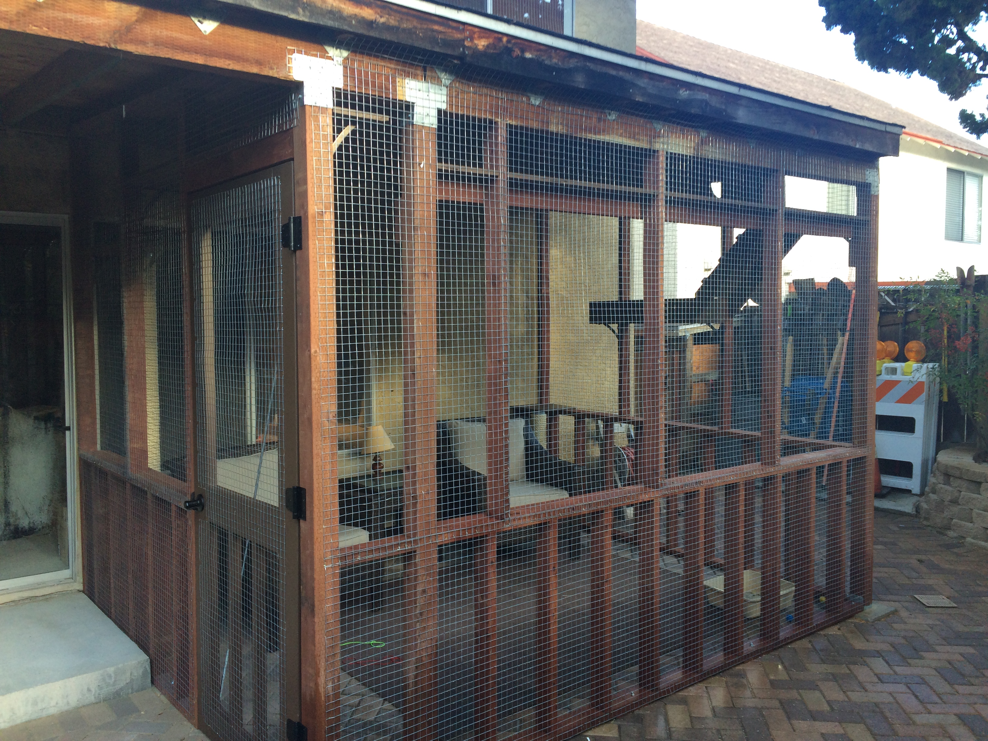
Finally, having a little “cat door” is essential because you want the cats to enjoy the space when they want to. And you don’t want them bugging you. There are many kinds of animal doors available, and I chose one that had a magnetic strip which keeps the door vertical when not in use, plus a 4-way lock (open, locked both ways, locked in, locked out). Some come with an RFID chip that you put on your cat and the door allows only your cat to go in and out, but that was way too fussy for me.
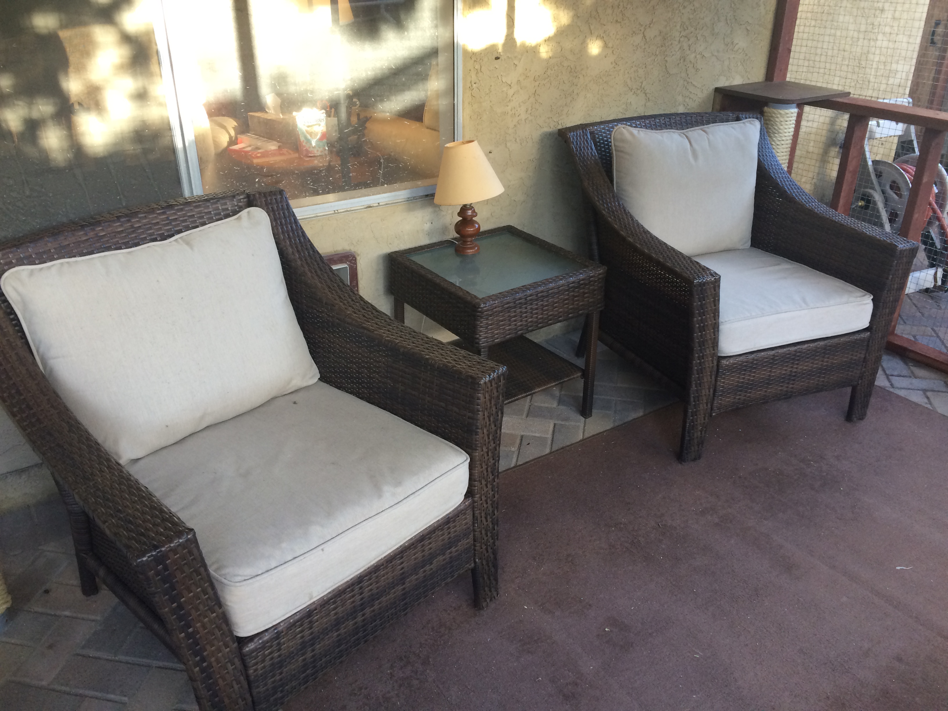
The catio makes an elegant (well, at least consonant) outdoor space where we can enjoy our cats and the outdoors together. Is it cocktail hour?
The finished product. Suitable for human and beast.
The catio should be appealing to both cats and their caretakers.
A catio should be a place where the cat caretakers can enjoy the space along with the cats. Cats like human companionship, and we can share and enjoy this space with each other.
Things are beginning to shape up in front, and one of the final “projects” was going to be to pour the concrete. This is DEFINITELY a job for a professional crew — NOT DIY! I know this from harsh, personal experience. Oh, I know, the videos make it seem really easy, but trust me, striking off a mound of concrete with a screed is hard, messy work, and is actually quite comical if it’s just you and your wife doing it. OK, I’ve done a couple of small sidewalks, but this job is way too large and intricate to trust to anybody but a professional crew. Hey, at least give me credit for knowing the difference!
Be that as it may, I had my plans, so I know what I wanted to do. Well, at least I thought that I did at the beginning. More on that later. The fact is that a dedicated DIY’er can do essentially all of the prep work. This is quite a lot of work, it turns out, and while you may get some benefit of saving some money, the biggest advantage for me was giving the concrete subcontractor a lot of flexibility with the schedule. If you have a pro do the whole job (demolition, site and grade prep, base fill, building the concrete forms, and setting out the remesh), then you’ll have to wait several weeks until the schedule is clear for a multi-day (or week) job. If you do all of the work, it’s a 1 day job of pouring and finishing the concrete, which can be scheduled more easily. Now for all of that prep work.
Demolition was done previously, per several of my previous posts. And, although I did a reasonable job of getting the grade set correctly with the steer skid, I still had a fair amount of cleanup to do. The skid steer doesn’t get into the corners, plus I had to get some stumps ground after I had completed the initial excavation. Plus the rains over the winter (such as they were) ended up “displacing” some dirt which had to be “re-placed”. In other words moved around some more. I ended up barrowing out about 4-5 yards of dirt to the back.
Will I EVER get rid of this dirt?
The next thing to do was to set up a base. I had a choice between 3/4″ gravel and “class II road base”. I decided to use gravel because I though it might be better, but it turns out that class II road base is what is typically used around here because gravel is used for areas where frost heave is a problem, and you want something to absorb the resulting ground motion. Road base is less expensive (!), and since it compacts way better, I plan on using it as the base for my brick-on-sand patio. So I find this out too late and I now have 7 yards of gravel to chuck and spread around. C’est la vie! Fortunately this went reasonably quickly. The only hiccup was that I had to somehow figure out a way to get wheelbarrows of this stuff to the back while navigating around previously installed drainage pipes that were annoyingly protruding from the ground. My solution was to barrow a pile of gravel around the drains and then take some plywood and make little ramps so that I could gingerly push a wheelbarrow with several hundred pounds of gravel through the maze that eventually lead to the back yard. After all was distributed, I rented a plate compactor to give a good solid base. Because the compactor wouldn’t fit into the corners, or around some of the obstacles sticking up, I had to use a hand compactor to get everything nice and tight.
That there is a cubic butt ton of gravel to move!
Chucking gravel from front to back. Note the plywood highway.
I used a pile of gravel and some plywood ramps to navigate around the drain grates that were sticking up. I ended up raking the gravel level as i worked my way back, so it ended up all good.
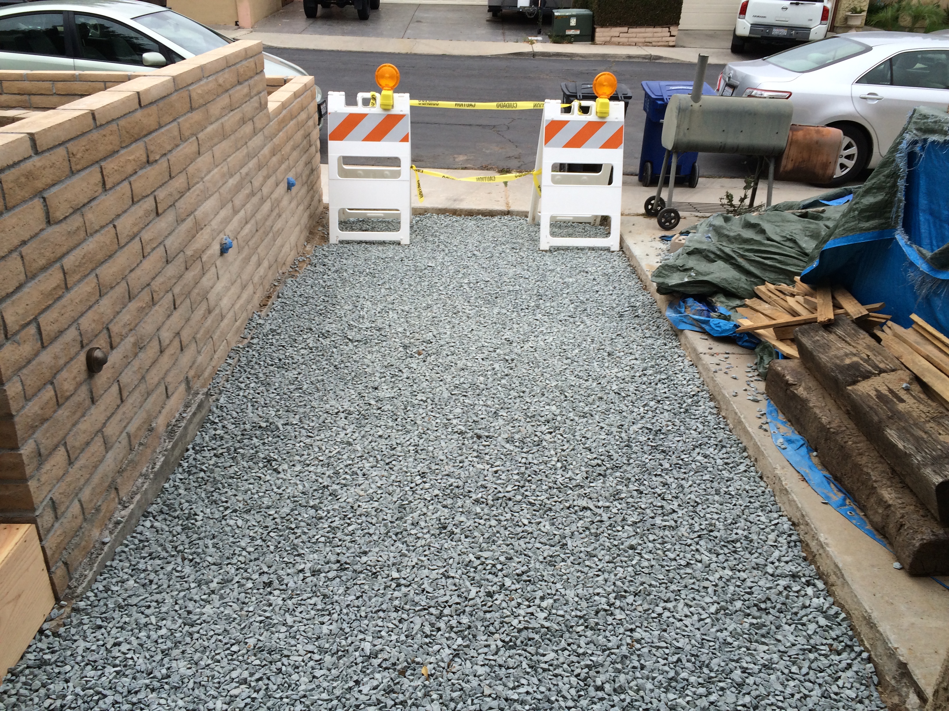
Front entrance gravel all level and compact. Ready for the forms.
While I was gearing up to move all of this gravel, I also had to buy lumber for the forms. So, I woke up early on a Saturday and headed over to the local Home Depot. Alas, it was raining, so it promised to be a mucky day outside. As I drove into the parking lot, I saw that the rental truck was conveniently parked, so I assumed it was available. I loaded up a bunch of lumber (plywood, 2x4s.), paid for it, and tried to rent the truck. I was then told it was out of commission for some obscure reason. Since my mood sufficiently sour to begin with, I vented my frustration. The customer service people were very nice, let me have my say, then proceeded to help me out with a free delivery. How good is that? So, shame on me for being a dickhead, but good for the Home Depot folks. I sent their boss a nice e-mail apologizing for my brief outburst and profusely thanking them for their excellent customer service. At any rate, I come back to the house and discover that my brand new wheelbarrow has a flat tire that will not succumb to mere inflation. So it’s back to Home Depot to get a flat-free tire. I guess it just was going to be one of those days….
My new wheelbarrow with a flat tire. Come on!
Next was the forms. With my previous experiences with concrete, getting the forms right was always a challenge. So this time, I wanted to make them very sturdy and straight. I used 1/2″ plywood and made a frame of 2x4s to support the plywood so there would be no bending. The 2×4 frames also gave me something solid to work with so when I drove the stakes, I would be using the forms as the guide. The contractors who came out to bid basically said that this was overkill, and they may have been right. But as a DIY guy working alone, I think this gave me the best result and minimized the amount of fussing around to get the forms aligned and in place.
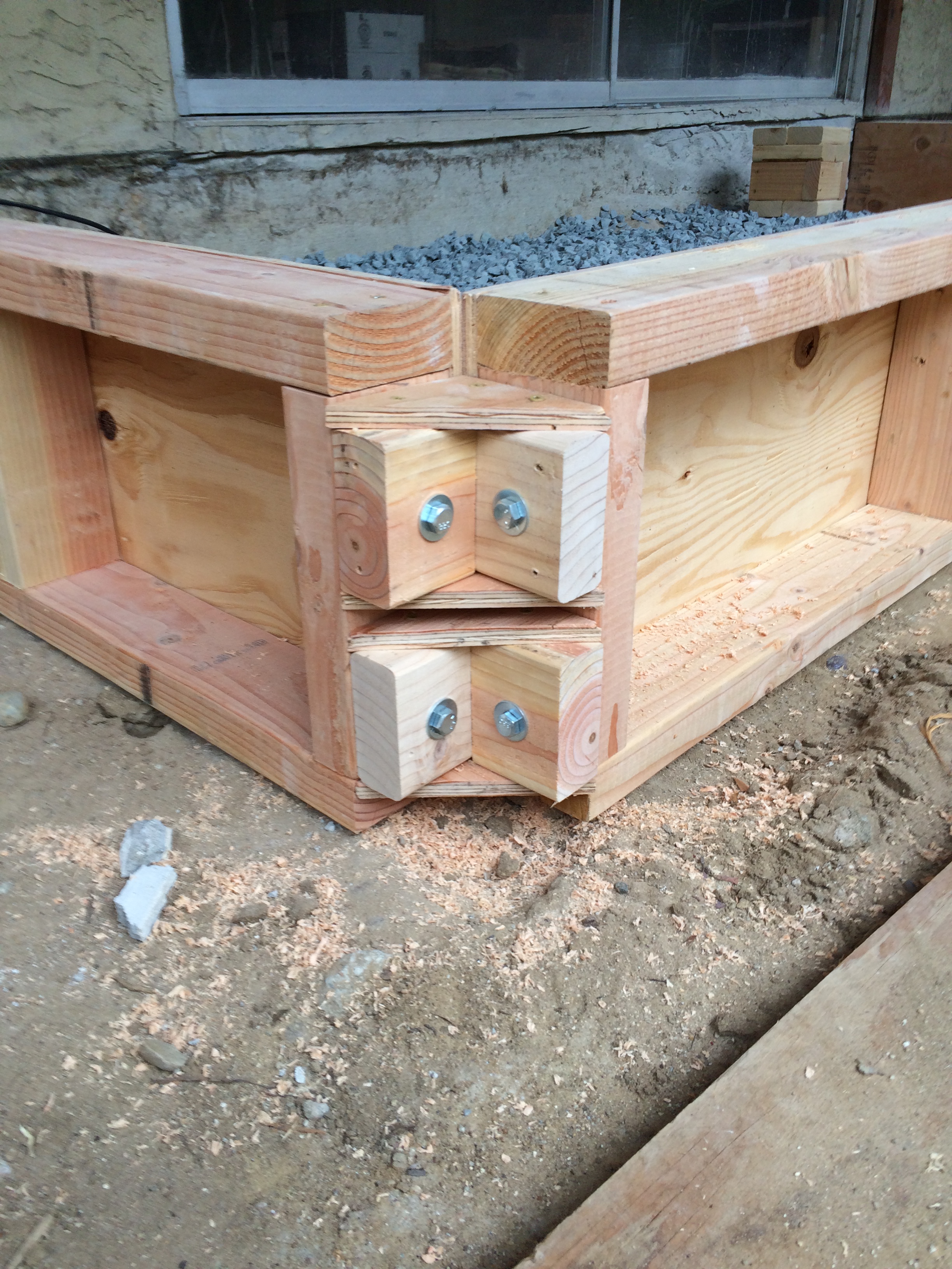
Frame for the form. I had to eventually rebuild this one because it was too large, but you get the idea.
Detail of my forms. The corners are bolted together with braces that pull everything tight and square, and make disassembly very easy. Too bad I won’t be using these again.
Bottom of plywood on form extends down to allow for concrete to flow between levels to allow a monolithic slab without a lot of fuss in removing the form to finish the faces.
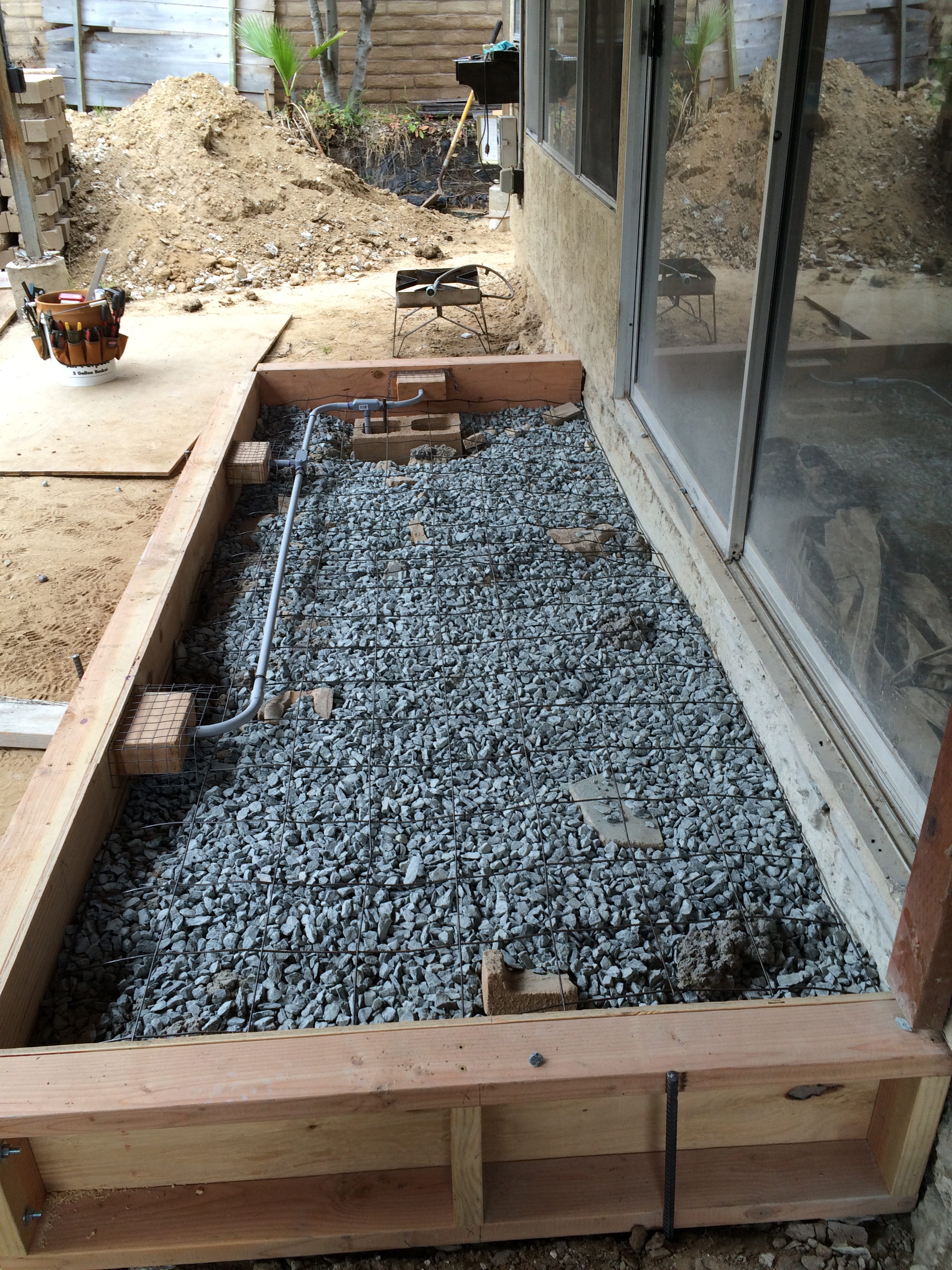
One of the nuances of my design was that I wanted to place can lights within the concrete to provide lighting for the steps (as a safety feature). Although the lights that I chose were rated for casting in concrete, in the long run, that is a bad idea because when (not if) they fail, you’ll have to tear out the concrete to get to them. No thanks. So, my plan was to construct plywood molds that would result in a perfectly sized recess that I could fit the lights into. Additionally, the molds had a hole that accepted PVC conduit, so that I could run the wiring between the boxes and back out through the wires that I had cleverly routed around the house while I was digging the drainage lines to supply the power. This is 12v lighting, so no problem with running the wires adjacent to where water might be. However, on the back porch, the lights needed to be located near the top of the slab. This could be problematic with cracking, so I added a 1×1 wire mesh reinforcement with material I had left over from a previous project. I also knocked down the sharp edges of the plywood boxes to minimize stress concentrations. My hope is that, with these little details, plus the fact that I am going to tile over these fragile areas, will make everything all right.
After I had set up the forms, I and my wife had a good chance to look at what the final result might be and, you guessed it, we were having some reservations. So, we took a step back, and perhaps some steps around, and started to actually walk through the expected traffic patterns. After a few iterations, it became obvious that we had to change things around a little in the front, and that is one of the advantages of DIY. You really can change things at almost the last-minute without a great impact on cost or schedule. Had this been an agreed upon design and had I already had a contractor doing the work, changing this stuff would have been out of the question. Of course, perhaps my design was not so good to begin with, and maybe a pro would have come up with the right answer in the first place, but what fun is that? I also had to re-design (and re-build) the forms to have the proper height above the finished concrete surface and provide a gap underneath so that the pour could be continuous, resulting in a monolithic slab. Good thing I had ordered some extra lumber!
The front landing is disjointed and not ergonomic. It looked better in the model and plans.
Just doesn’t look right.
That’s more like it! Nicely balanced and allows access up the ramp (on the right), from the driveway apron (on the left), and from the garage.
While I was doing all of this, it was time to get some bids for the work. I had a number of folks come by, and each was very helpful and offered some advice as I was finishing up. One comment was pretty much universal: “Fill in the areas where you have deep concrete (e.g. the back porch and front landing) with materials that are less expensive than concrete. Well, it turns out that I had a big pile of masonry detritus accumulated from my previous work, so it was a no-brainer to chuck that stuff into these areas, if not to save money, than to just get rid of the stuff in a manner that did not involve surreptitiously dumping this crap into the residential waste stream over a long period of time. Which is my normal modus operandi. I learned this from my wife.
Finally, the re-mesh. This is a welded wire mesh that is used to provide reinforcement in the concrete. It is made of large gauge (#6) steel wires that are spot welded together to form a 6″x6” mesh. You can buy these in flat sheets of 5’x8′, but that is much more expensive than buying a 150′ roll and cutting it yourself. Of course, I did the latter. I had previously purchased a heavy-duty wire cutter (essential for this work) and set about unrolling the beast and nipping off sections so that they fit where I needed to put them. I ended up with a number of relatively small pieces because (a) they were easier to make flat — the roll has some “memory” so you have to bend it a little to make it lie flat — and (b) they were easier to handle and place where I needed them.
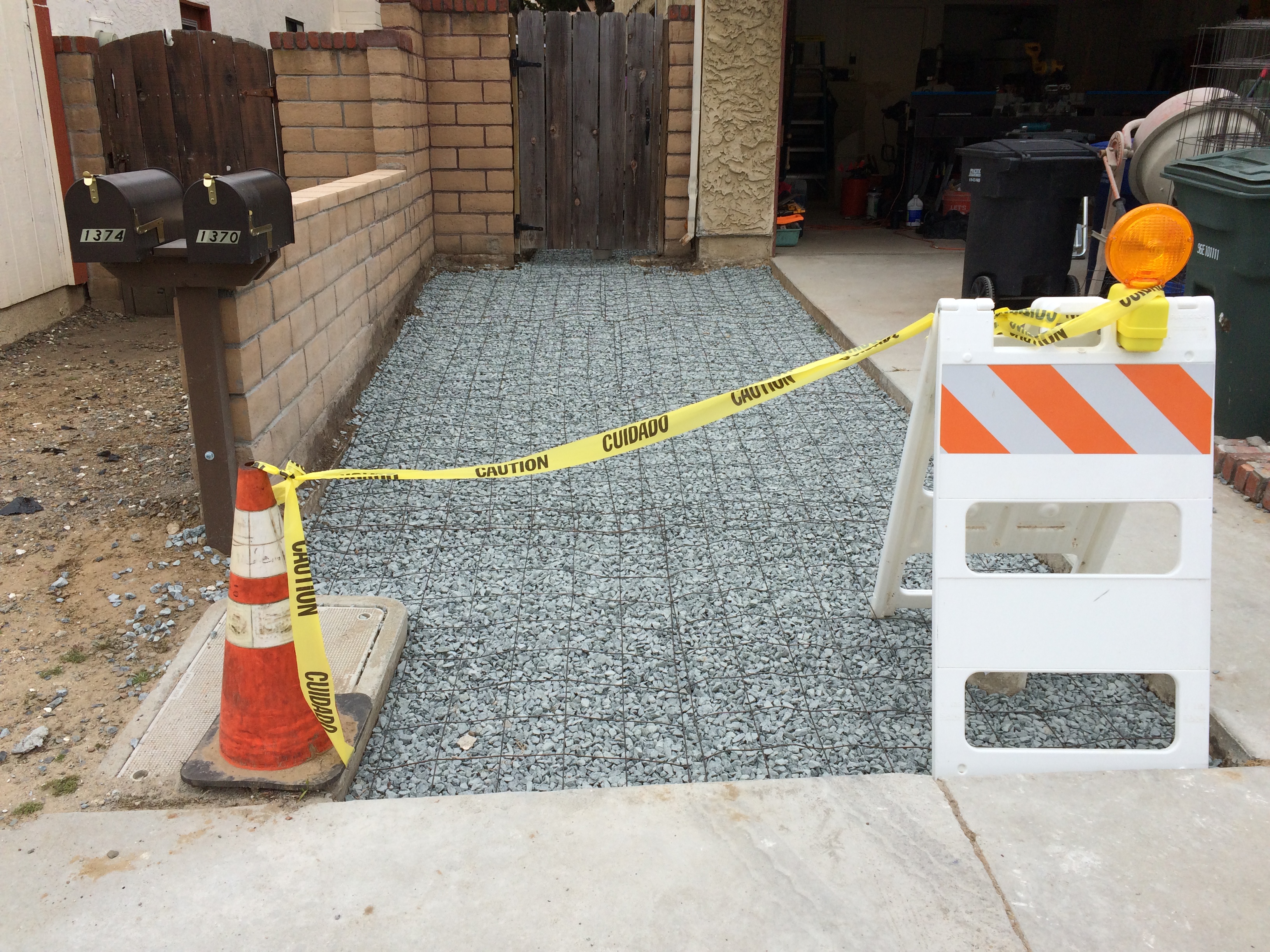
Back porch ready for the pour. Can you see the masonry detritus poking through the gravel? Also a good look at the forms and reinforcement for the can lights.
Left driveway apron all ready for the pour.
PVC electrical conduit is supported by rebar stakes so that it won’t bend when the concrete is poured over it.
Service sidewalk all ready. I’m replacing the square grates with round ones on the advice of the subcontractor to minimize cracking.
Now everything was all set and the bids were in. It was time to choose a subcontractor. I chose a person who (a) provided a reasonable price (part of my day job is cost estimation, so I knew what the price range should be), and (b) would provide a schedule (e.g., meeting time, estimates), and stick to it. I believe the latter is a key indicator of future performance.
I’m meeting with the subcontractor tomorrow, and with luck, I’ll have the concrete poured by the end of the week. Wish me luck!
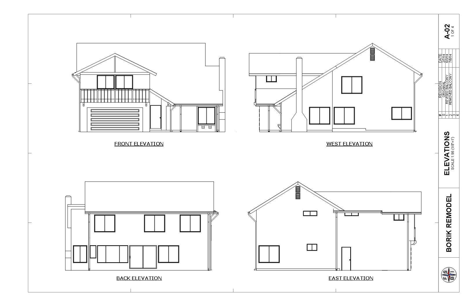
After the architectural design was complete, the next step was to actually figure out how to construct it. My plans needed to be detailed enough for the city building department to approve them. At first blush, one might think that pushing out a bedroom by seven feet is no big deal. Throw together a few trusses, use the existing flooring, build some walls with holes in them for windows, and you’re done.
Well, not really. The short story is that building codes have advanced, and when you build an addition, you are actually going to build a carefully engineered structure. If you’re really not a die hard DIY and/or don’t have any background or training in structural engineering or construction, then your best bet is to hire a designer to do the work. They aren’t cheap (I got a quote for $7,500 minimum), but it may be worth it, depending on the complexity of your project. Having said that, you don NOT have to be a structural engineer to design an addition , or any other structure for that matter. All you have to do is follow the prescriptive methods contained in the applicable codes. This is essentially a “cookbook” method of designing a structure that includes a number of safety factors such that a design using these methods will withstand loads and stresses (people, wind, earthquake, etc.) that are expected for a residential home in a specific location. Here is where you can benefit from my experience. DO NOT try to get all fancy and design something that is not clearly specified in the codes and deviates from the “cookbook recipe”, then you will have to get a sign-off by a licensed Professional Engineer (P.E.). Again, this is expensive, and probably not worth it for a smaller project. So if you’re willing to spend some study time (and maybe even learn something!), a DIY solution awaits!
The best place to start is the building code that is applicable to your jurisdiction. The California Residential Code is actually reasonably easy to follow, but I found the American Wood Council Wood Frame Construction Manual (WFCM) a better resource for my purposes. Since the California Residential Code allows it, that is what I used. What really made a difference and put it all together for me was the WFCM Workbook, which has an example home design that steps you through the process. You will also have to determine the environmental conditions that your structure will need to withstand. This includes maximum wind conditions, seismic design category, whether or not you’re in a flood zone, maximum and minimum temperatures, termite infestation likelihood, and other factors. These are usually spelled out in the code and it makes sense to put together a little table for yourself so that you can refer to it when bouncing back and forth between the various parts of the code to get your numbers.
The approach that I used, which was taken directly from the WFCM workbook, was to start at the top and work my way down from the roof to the foundation. At each step you not only have to specify the materials (trusses, roof underlayment, studs, joists, etc.), but you ALSO need to show how these elements are connected. The code gives a table of fasteners (mainly nails) for fastening framing and sheathing, but when it comes to connecting major assemblies to each other, you typically have to use engineered specialty connectors (for example, roof truss to wall top plate). You have to be able to show, step by step, that the loads from each element are transferred through successive elements all the way to the foundation. So, roof to wall, wall to floor, floor to wall, wall to foundation.
A quick word about fasteners. The common nail is a very nuanced component. There are many types of many materials, and it is IMPORTANT that you use the right nail for the right purpose. The tables in the code tell you what to do, but therein are requirements for not only nail type, but spacing, and orientation, e.g., toe nail vs. face nail. Bigger and more is not necessarily better because you risk splitting the underlying wood member. So follow the instructions! In general, nails are better than screws, especially for framing. This is because they have significantly higher shear strength, and have some ductility which means that they will “give” a bit in a storm or an earthquake whereas screws tend to be brittle. Not that screws are bad. Just don’t use them for framing or shear walls. An exception to this are structural wood screws (SWS). These are larger screws made of heat treated steels that have higher quality control than your run-of-the-mill screw. The manufacturers of these screws have data sheets which detail their application. I used them in some places, a ledger board for example, but in general, I stuck with nails when I could.
One thing that was scary for me at the last was trying to figure out how to retrofit concrete anchors to bring the addition into compliance with seismic requirements. Fortunately, the folks who make these connectors also provide a method of anchoring these connectors with special epoxy into existing concrete. The only “downside” is that I have to have a certified inspector sign off on the installation. Well, maybe not a downside as it really has to be right. Just additional expense.
Although I spent many months getting to this point, and went down a few “rabbit holes”, I can definitely say that the effort was worth it, especially as a DIY’er. The process of designing showed me how to build it with all of the right materials, methods, and references. It’s going to be really pro!
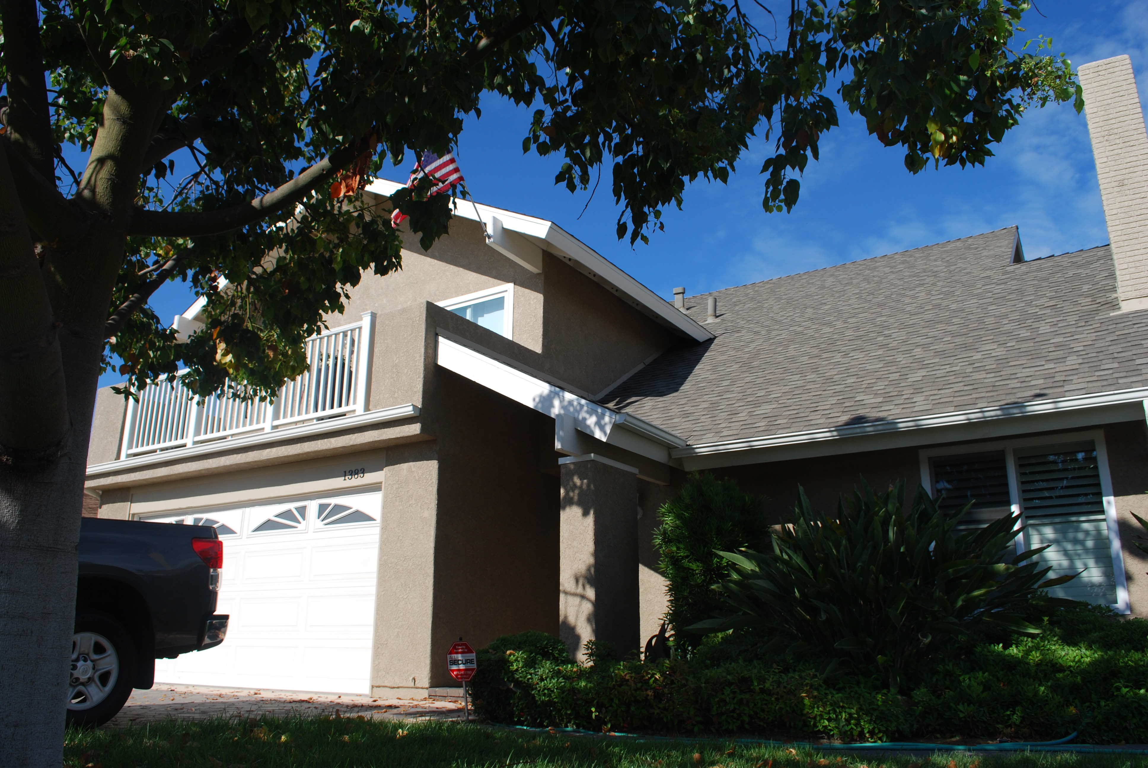
One of the major reasons I started this project was the fact that I had an annoying leak from the roof that was making a big stain on the ceiling in my living room. The leak really comes from a second floor balcony which is adjacent to the master bedroom. The design is poor because water accumulates from the roof and concentrates in the balcony, and there is no easy way for the water to run off. So it stays in the balcony and ultimately leaks onto the porch, the garage, and the living room. I tried three different ways to fix the floor of the balcony (tile, flat roofing, and rubber membrane), and none of them worked. In looking around the rest of the neighborhood with houses of similar design, I noted that they also had the same problem.
ORIGINAL BALCONY DESIGN
So another approach was necessary. Fortunately, a few of the houses had a modification that put a valley roof directly above the porch. I asked the owners if that helped and they all said that it completely solved the leakage problem.
ROOF OVER FRONT PORCH-1
ROOF OVER FRONT PORCH 2
That being said, the balcony itself was just wasted space. It was hot in the afternoon because it faces South West, and it has an expansive view of the garages of my neighbors across the street. Not exactly a place where I’d hang out and relax. So, to make more out of the space, I decided to see what it took to completely eliminate the balcony and expand the master bedroom. There were some homes in the neighborhood that had done that, but I didn’t like the outcome because they didn’t fix the leakage problem. Plus, I wanted to reconfigure the windows to provide better air flow and noise mitigation, and I wanted to rearrange the master bathroom and closet to provide a more open floor plan.
EXPANDED MASTER BEDROOM
So, I looked at my original floor plan, and went back to the type of functionality we wanted. We decided to utilize the new space in an open manner, swap the location of the toilet and lavatory, make a small “room” for the toilet area with folding doors, and enable a natural flow from the bathroom to the dressing area. The dressing area would be open, yet private, and have some nice light coming in from the new windows. We also have some room for a sitting area and our desks. Simple and straightforward, but it looks pretty nice. At least from the plans! I think it meets our requirements for making the most out of wasted space and provides a permanent fix for the roof leak.